
PCA9685 4-Channel 8W Open Collector FET Driver 4-Channel GPIO w/ I2C Interface Datasheet


PCA9685 All information provided in this document is subject to legal disclaimers. © NXP Semiconductors N.V. 2015. All rights reserved.
Product data sheet Rev. 4 — 16 April 2015 2 of 52
NXP Semiconductors
PCA9685
16-channel, 12-bit PWM Fm+ I
2
C-bus LED controller
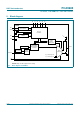
The active LOW Output Enable input pin (OE) allows asynchronous control of the LED
outputs and can be used to set all the outputs to a defined I
2
C-bus programmable logic
state. The OE
can also be used to externally ‘pulse width modulate’ the outputs, which is
useful when multiple devices need to be dimmed or blinked together using software
control.
Software programmable LED All Call and three Sub Call I
2
C-bus addresses allow all or
defined groups of PCA9685 devices to respond to a common I
2
C-bus address, allowing
for example, all red LEDs to be turned on or off at the same time or marquee chasing
effect, thus minimizing I
2
C-bus commands. Six hardware address pins allow up to
62 devices on the same bus.
The Software Reset (SWRST) General Call allows the master to perform a reset of the
PCA9685 through the I
2
C-bus, identical to the Power-On Reset (POR) that initializes the
registers to their default state causing the outputs to be set LOW. This allows an easy and
quick way to reconfigure all device registers to the same condition via software.
2. Features and benefits
16 LED drivers. Each output programmable at:
Off
On
Programmable LED brightness
Programmable LED turn-on time to help reduce EMI
1 MHz Fast-mode Plus compatible I
2
C-bus interface with 30 mA high drive capability
on SDA output for driving high capacitive buses
4096-step (12-bit) linear programmable brightness per LED output varying from fully
off (default) to maximum brightness
LED output frequency (all LEDs) typically varies from 24 Hz to 1526 Hz (Default of 1Eh
in PRE_SCALE register results in a 200 Hz refresh rate with oscillator clock of
25 MHz.)
Sixteen totem pole outputs (sink 25 mA and source 10 mA at 5 V) with software
programmable open-drain LED outputs selection (default at totem pole). No input
function.
Output state change programmable on the Acknowledge or the STOP Command to
update outputs byte-by-byte or all at the same time (default to ‘Change on STOP’).
Active LOW Output Enable (OE
) input pin. LEDn outputs programmable to logic 1,
logic 0 (default at power-up) or ‘high-impedance’ when OE
is HIGH.
6 hardware address pins allow 62 PCA9685 devices to be connected to the same
I
2
C-bus
Toggling OE
allows for hardware LED blinking
4 software programmable I
2
C-bus addresses (one LED All Call address and three LED
Sub Call addresses) allow groups of devices to be addressed at the same time in any
combination (for example, one register used for ‘All Call’ so that all the PCA9685s on
the I
2
C-bus can be addressed at the same time and the second register used for three
different addresses so that
1
⁄
3
of all devices on the bus can be addressed at the same
time in a group). Software enable and disable for these I
2
C-bus address.
Software Reset feature (SWRST General Call) allows the device to be reset through
the I
2
C-bus