
Data Sheet


AD5241/AD5242
Rev. C | Page 15 of 20
ADDITIONAL PROGRAMMABLE LOGIC OUTPUT
The AD5241/AD5242 feature additional programmable logic
outputs, O
1
and O
2
, that can be used to drive digital load, analog
switches, and logic gates. They can also be used as a self-contained
shutdown preset to Logic 0 that is further explained in the
Shutdown Function section. O
1
and O
2
default to Logic 0 during
power-up. The logic states of O
1
and O
2
can be programmed in
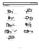
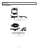
Frame 2 under the write mode (see Figure 4). Figure 34 shows
the output stage of O
1
, which employs large P-channel and N-
channel MOSFETs in push-pull configuration. As shown in
Figure 34, the output is equal to V
DD
or V
SS
, and these logic
outputs have adequate current driving capability to drive
milliamperes of load.
IN
1 2
V
DD
O
1
V
SS
M
P
M
N
O
1
DATA IN FRAME 2
OF WRITE MODE
00926-025
Figure 34. Output Stage of Logic Output, O
1
Users can also activate O
1
and O
2
in the following three different
ways without affecting the wiper settings:
1.
Start, slave address byte, acknowledge, instruction byte
with O
1
and O
2
specified, acknowledge, stop.
2.
Complete the write cycle with stop, then start, slave address
byte, acknowledge, instruction byte with O
1
and O
2
specified,
acknowledge, stop.
3.
Do not complete the write cycle by not issuing the stop,
then start, slave address byte, acknowledge, instruction
byte with O
1
and O
2
specified, acknowledge, stop.
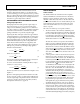
All digital inputs are protected with a series input resistor and
the parallel Zener ESD structures shown in Figure 36. This
applies to the digital input pins, SDA, SCL, and
SHDN
.
SHUTDOWN FUNCTION
Shutdown can be activated by strobing the
SHDN
pin or
programming the SD bit in the write mode instruction byte (see
). If the RDAC Register 1 or RDAC Register 2 (AD5242
only) is placed in shutdown mode by the software, SD bit, the
part returns the wiper to its prior position when a new command
is received.
Table 2
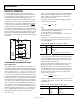
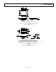
In addition, shutdown can be implemented with the device digital
output, as shown in Figure 35. In this configuration, the device
is shutdown during power-up but users are allowed to program
the device. Thus, when O
1
is programmed high, the device exits
shutdown mode and responds to the new setting. This self-contained
shutdown function allows absolute shutdown during power-up,
which is crucial in hazardous environments, and it does not add
extra components.
SDA
SHDN
SCL
R
PD
O
1
0
0926-026
Figure 35. Shutdown by Internal Logic Output, O
1
340
Ω
LOGIC
V
SS
00926-027
Figure 36. ESD Protection of Digital Pins
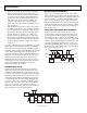
A
,B,W
V
SS
00926-028
Figure 37. ESD Protection of Resistor Terminals