
Data Sheet

www.austriamicrosystems.com/LED-Driver-ICs/AS1115 Revision 1.08 5 - 25
AS1115
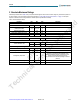
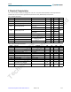
Datasheet - E l e c t rica l C h a racte r i s tics
Note: The Min / Max values of the Timing Characteristics are guaranteed by design.
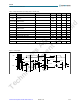
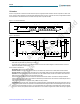
F
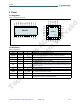
igure 3. Timing Diagram
Table 5. Timing Characteristics (C
B
= 550pF (max) on each Bus Line)
Symbol Parameter Conditions Min Typ Max Unit
fSCL
SCL Frequency
1 MHz
tBUF
Bus Free Time Between STOP and START
Conditions
500 ns
tHOLDSTART
Hold Time for Repeated
START Condition
260 ns
tLOW
SCL Low Period
50
0 ns
tHIGH
SCL High Period
260 ns
tSETUPSTART
Setup Time for Repeated
START Condition
260 ns
tSETUPDATA
Data Setup Time
50 ns
tRISE
SDA + SCL Rise Time
120 ns
tFALL
SDA + SCL Fall Time
120 ns
tSETUPSTOP
STOP Condition Setup Time
260 ns
tSPIKESUP
Pulse Width of Spike Suppressed
50 ns
Key Readback
Debounce Time 20 ms
Repeated
START
SDI
SCL
STARTSTOP
tBUF
tLOW
tHOLDSTART
tHOLDDATA
tR
tHIGH
tF
tSETUPDATA
tHOLDSTART
tSPIKESUP
tSETUPSTOP
tSETUPSTART
ams AG
Technical content still valid