
Data Sheet

www.austriamicrosystems.com/LED-Driver-ICs/AS1115 Revision 1.08 15 - 25
AS1115
Datasheet - D e t a iled D e s c r iptio n
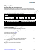
I²C Self Addressing
If this feature is used, 2 of the 16 key readback nodes can be left open or shorted for self-addressing. This is done with KEYA together with
SEGG (A0) and SEGF (A1). This two nodes cannot be used for key-readback in this case. After startup all devices have the predefined address
0000000. A single command for self addressing will update all connected AS1115. This command has to be done after startup or every time the
AS1115 gets disconnected from the supply. The I²C address definition must be done with fixed connection, since I²C detection is excluded from
debounce time of key registers.geht
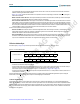
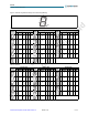
Note: A short writes a logical “0” whereas an open writes a logical “1” as address bit (see Figure 26).
Fig
ure 26. Address Coding
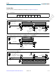
Keyscan Register
These two registers contain the result of the keyscan input of the 16 keys. To ensure proper results the data in these registers are updated only
if
the logic data scanned is stable for 20ms (debounce time). A change of the data stored within these two registers is indicated by a logic low on
the IRQ pin. The IRQ is high-impedance if a read operation on the key scan registers is started.
Note: If I²C self addressing is used segment G&F of KEYA is used for the two LSB of the I²C address. In this case these two nodes cannot be
used as a key. Additionally the debounce time is disabled for these two bits.
The data within the keyscan register is updated continuously during every cycle (1/10 of refresh rate). Therefore, to get a valid read-
back of keys it is recommended to read out the keyscan registers immediately after the IRQ is triggered. A short writes a logical “0”
whereas an open writes a logical “1” as keyscan register bit.
Note: If the blink_en bit (bit D4 in the Feature Register 0x0E) is set to ‘1’, the keyscan is not returning a valid value.
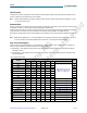
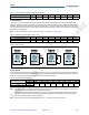
Table 11. No-Decode Mode Data Bits and Corresponding Segment Lines
D7 D6 D5 D4 D3 D2 D1 D0
Corresponding Segment Line DP A B C D E F G
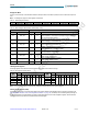
Table 12. Self Addressing Register (Address (HEX) = 0x2D))
D7 D6 D5 D4 D3 D2 D1 D0
Factory-set IC address X X X X X X X 0
User-set IC address X X X X X X X 1
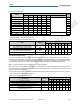
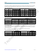
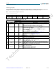
Table 13. LED Diagnostic Register Address
Register HEX Address
Segment
Key D7 D6 D5 D4 D3 D2 D1 D0
0x1C
KEYA
DP A B C D E F G
0x1D
KEYB
ams AG
Technical content still valid