
Data Sheet

www.austriamicrosystems.com/LED-Driver-ICs/AS1115 Revision 1.08 12 - 25
AS1115
Datasheet - D e t a iled D e s c r iptio n
Initial Power-Up
On initial power-up, the AS1115 registers are reset to their default values, the display is blanked, and the device goes into shutdown mode. At
this time, all registers should be programmed for normal operation.
Note: The default settings enable only scanning of one digit; the internal decoder is disabled and the Intensity Control Register (see page
17) is set to the minimum values.
Shutdown Mode
The AS1115 devices feature a shutdown mode, where they consume only 200nA (typ) current. Shutdown mode is entered via a write to the Shut-
do
wn Register (see Table 7). During shutdown mode the Digit-Registers maintain their data.
Shutdown mode can either be used as a means to reduce power consumption or for generating a flashing display (repeatedly entering and leav-
ing shutdown mode). For minimum supply current in shutdown mode, logic input should be at GND or VDD (CMOS logic level).
When entering or leaving shutdown mode, the Feature Register is reset to its default values (all 0s) when Shutdown Register bit D7 (page 13) =
0.
Note: When Shutdown Register bit D7 = 1, the Feature Register is left unchanged when entering or leaving shutdown mode. If the AS1115
is used with an external clock, Shutdown Register bit D7 should be set to 1 when writing to the Shutdown Register.
Digit- and Control-Registers
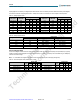
The AS1115 devices contain 8 Digit-Registers,11 control-registers and 10 diagnostic-registers, which are listed in Table 6. All registers are
selected using a 8-bit address word, and communication is done via the I²C interface.
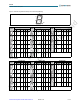
Digit Registers – These registers are realized with an on-chip 64-bit memory. Each digit can be controlled directly without rewriting the
whole register contents.
Control Registers – These registers consist of decode mode, display intensity, number of scanned digits, shutdown, display test and fea-
tures selection registers.
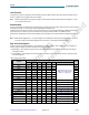
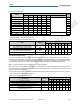
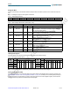
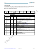
Table 6. Register Address Map
Type
Register
Address
Page
D15:D13 D12 D11 D10 D9 D8 D7:D0
Digit Register
Digit 0 000 0 0 0 0 1
(see Table 9 on page 14,
Table 10 on page 14 and
Table 11 on page 15)
N/A
Digit 1 000 0 0 0 1 0 N/A
Digit 2 000 0 0 0 1 1 N/A
Digit 3 000 0 0 1 0 0 N/A
Digit 4 000 0 0 1 0 1 N/A
Digit 5 000 0 0 1 1 0 N/A
Digit 6 000 0 0 1 1 1 N/A
Digit 7 000 0 1 0 0 0 N/A
Control Register
Decode-Mode 000 0 1 0 0 1 (see Table 8 on page 13) 13
Global Intensity 000 0 1 0 1 0 (see Table 17 on page 17) 17
Scan Limit 000 0 1 0 1 1 (see Table 19 on page 17) 17
Shutdown 000 0 1 1 0 0 (see Table 7 on page 13) 12
Self Addressing 001 0 1 1 0 1 N/A
Feature 000 0 1 1 1 0 (see Table 20 on page 18) 18
Display Test Mode 000 0 1 1 1 1 (see Table 14 on page 16) 13
DIG0:DIG1 Intensity 000 1 0 0 0 0 (see Table 18 on page 17)
DIG2:DIG3 Intensity 000 1 0 0 0 1 (see Table 18 on page 17)
DIG
4:DIG5 Intensity 000 1 0 0 1 0 (see Table 18 on page 17)
DIG6:DIG7 Intensity 000 1 0 0 1 1 (see Table 18 on page 17)
ams AG
Technical content still valid