
Data Sheet

© 2009 Microchip Technology Inc. DS22226A-page 21
MCP3426/7/8
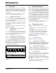
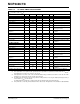
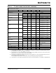
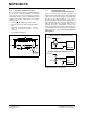
TABLE 5-3: ADDRESS BITS VS. ADDRESS
SELECTION PINS FOR
(MCP3427 AND MCP3428
ONLY) (NOTE1,2,3)
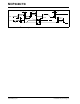
5.3.3 WRITING A CONFIGURATION BYTE
TO THE DEVICE
When the Master sends an address byte with the R/W
bit low (R/W = 0), the device expects one configuration
byte following the address. Any byte sent after this
second byte will be ignored. The user can change the
operating mode of the device by writing the
configuration register bits.
If the device receives a write command with a new
configuration setting, the device immediately begins a
new conversion and updates the conversion data.
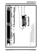
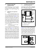
FIGURE 5-3: Timing Diagram For Writing To The MCP3426/7/8.
I
2
C Device
Address Bits
Logic Status of Address
Selection Pins
A2 A1 A0 Adr0 Pin Adr1 Pin
0000 (Addr_Low) 0 (Addr_Low)
0010 (Addr_Low) Float
0100 (Addr_Low) 1 (Addr_High)
1001 (Addr_High) 0 (Addr_Low)
1011 (Addr_High) Float
1101 (Addr_High) 1 (Addr_High)
011Float 0 (Addr_Low)
111Float 1 (Addr_High)
000Float Float
Note 1: Float: (a) Leave pin without connecting to
anything (left floating), or (b) apply
Addr_Float voltage.
2: The user can tie the pins to V
SS
or V
DD
:
- Tie to V
SS
for Addr_Low
- Tie to V
DD
for Addr_High
3: See Addr_Low, Addr_High, and
Addr_Float parameters in Electrical
Characteristics Table.
9
1
9
1
Stop Bit by
11
0
1A2
A1 A0
R/W
ACK by
MCP3426/7/8
RDY
C1 C0
O
/C
S1 S0 G1 G0
1st Byte:
2nd Byte:
Master
ACK by
MCP3426/7/8
Address Byte
Configuration Byte
Start Bit by
Master
with Write command
Note: – Stop bit can be issued any time during writing.
– MCP3426/7/8 device code is 1101 (programmed at the factory).
– See Figure 5-1 for details in Address Byte.
SCL
SDA
(a) One-Shot Mode: 1
(b) Continuous Mode: not effected