
Data Sheet

© 2009 Microchip Technology Inc. DS22226A-page 19
MCP3426/7/8
If the configuration byte is read repeatedly by clocking
continuously after reading the data bytes (i.e., after the
4th byte in the 16-bit conversion mode), the state of the
RDY
bit indicates whether the device is ready with new
conversion result. When the Master finds the RDY bit is
cleared, it can send a not-acknowledge (NAK) bit and
a stop bit to exit the current read operation and send a
new read command for the latest conversion data.
Once the conversion data has been read, the ready bit
toggles to ‘1’ until the next new conversion data is
ready. The conversion data in the output register is
overwritten every time a new conversion is completed.
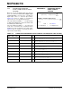
Figure 5-3 shows an example of writing configuration
register, and Figure 5-4 shows an example of reading
conversion data. The user can rewrite the configuration
byte any time for a new setting. Table 5-1 and Tab le 5-
2 show the examples of the configuration bit operation.
5.3 I
2
C Serial Communications
The device communicates with the Master
(microcontroller) through a serial I
2
C (Inter-Integrated
Circuit) interface and support standard (100 kbits/sec),
fast (400 kbits/sec) and high-speed (3.4 Mbits/sec)
modes. The serial I
2
C is a bidirectional 2-wire data bus
communication protocol using open-drain SCL and
SDA lines.
The device can only be addressed as a slave. Once
addressed, it can receive configuration bits with a write
command or transmit the latest conversion results with
a read command. The serial clock pin (SCL) is an input
only and the serial data pin (SDA) is bidirectional. The
Master starts communication by sending a START bit
and terminates the communication by sending a STOP
bit. In read mode, the device releases the SDA line
after receiving NAK and STOP bits.
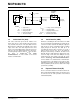
An example of a hardware connection diagram is
shown in Figure 6-1. More details of the I
2
C bus
characteristic is described in Section 5.6 “I
2
C Bus
Characteristics”.
5.3.1 I
2
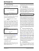
C DEVICE ADDRESSING
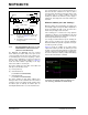
The first byte after the START bit is always the address
byte of the device, which includes the device code (4
bits), address bits (3 bits), and R/W
bit. The device
code for the devices is 1101, which is programmed at
the factory. The I
2
C address bits (A2, A1, A0 bits) are
as follows:
• MCP3426: Programmed at factory
• MCP3427 and MCP3428: Progammed by the
user. It is determined by the logic status of the two
external address selection pins on the user’s
application board (Adr0 and Adr1 pins). The
Master must know the Adr0 and Adr1 pin
conditions before sending read or write command.
See Section 5.3.2 “Device Address Bits (A2,
A1, A0) and Address Selection Pins (MCP3427
and MCP3428)” for more details
Figure 5-1 shows the details of the address byte.
The three I
2
C address bits allow up to eight devices on
the same I
2
C bus line. The (R/W) bit determines if the
Master device wants to read the conversion data or
write to the Configuration register. If the (R/W) bit is set
(read mode), the device outputs the conversion data in
the following clocks. If the (R/W
) bit is cleared (write
mode), the device expects a configuration byte in the
following clocks. When the device receives the correct
address byte, it outputs an acknowledge bit after the
R/W
bit.
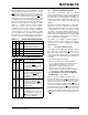
TABLE 5-1: WRITE CONFIGURATION BITS
R/W O/C RDY Operation
000No effect if all other bits remain
the same - operation continues
with the previous settings.
001Initiate One-Shot Conversion.
010Initiate Continuous Conversion.
011Initiate Continuous Conversion.
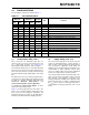
TABLE 5-2: READ CONFIGURATION BITS
R/W O/C RDY Operation
100New conversion result in One-
Shot conversion mode has just
been read. The RDY
bit remains
low until set by a new write
command.
101One-Shot Conversion is in prog-
ress. The conversion result is not
updated yet. The RDY
bit stays
high until the current conversion
is completed.
110New conversion result in
Continuous Conversion mode
has just been read. The RDY
bit
changes to high after reading the
conversion data.
111The conversion result in
Continuous Conversion mode
was already read. The next new
conversion data is not ready. The
RDY
bit stays high until a new
conversion is completed.