
Data Sheet


LOAD
V
SUPPLY
R
SHUNT
40kW
40kW
40kW
40kW
INA152
+5V
V
OUT
+2.5V
V
REF
V
IN+
V
IN-
V+ V+
+5V
OUT
OUT
INA193-INA198
V
IN+
V
IN-
+5V
INA193-INA198
INA193
,
INA194
,
INA195
INA196
,
INA197
,
INA198
SBOS307G –MAY 2004–REVISED JANUARY 2015
www.ti.com
9 Application and Implementation
NOTE
Information in the following applications sections is not part of the TI component
specification, and TI does not warrant its accuracy or completeness. TI’s customers are
responsible for determining suitability of components for their purposes. Customers should
validate and test their design implementation to confirm system functionality.
9.1 Application Information
The INA193-INA198 devices measure the voltage developed across a current-sensing resistor when current
passes through it. The ability to have shunt common-mode voltages from −16-V to +80-V drive and control the
output signal with Vs offers multiple configurations, as discussed throughout this section.
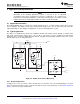
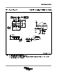
9.2 Typical Application
The device is a unidirectional, current-sense amplifier capable of measuring currents through a resistive shunt
with shunt common-mode voltages from −16 V to 80 V. Two devices can be configured for bidirectional
monitoring and is common in applications that include charging and discharging operations where the current
flow-through resistor can change directions.
Figure 29. Bi-Directional Current Monitoring
9.2.1 Design Requirements
Vsupply is set to 12 V, Vref at 2.5 V and a 10-mΩ shunt. The accuracy of the current will typically be less than
0.5% for current greater than ±2 A. For current lower than ±2 A, the accuracy will vary; use the Device Functional
Modes section for accuracy considerations.
22 Submit Documentation Feedback Copyright © 2004–2015, Texas Instruments Incorporated
Product Folder Links: INA193 INA194 INA195 INA196 INA197 INA198