
Data Sheet

R
S
Load
V
IN+
-16Vto+80V
I
S
V
IN+
V
IN-
+2.7Vto+18V
V+
OUT
INA193-INA198
R
1
R
L
R
2
INA193
,
INA194
,
INA195
INA196
,
INA197
,
INA198
SBOS307G –MAY 2004–REVISED JANUARY 2015
www.ti.com
8.3 Feature Description
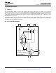
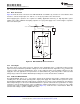
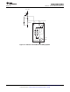
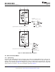
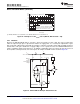
8.3.1 Basic Connection
Figure 20 shows the basic connection of the INA193-INA198. To minimize any resistance in series with the shunt
resistance, connect the input pins, V
IN+
and V
IN−
, as closely as possible to the shunt resistor.
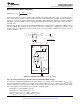
Power-supply bypass capacitors are required for stability. Applications with noisy or high impedance power
supplies may require additional decoupling capacitors to reject power-supply noise. Connect bypass capacitors
close to the device pins.
Figure 20. INA193-INA198 Basic Connection
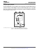
8.3.2 Selecting R
S
The value chosen for the shunt resistor, R
S
, depends on the application and is a compromise between small-
signal accuracy and maximum permissible voltage loss in the measurement line. High values of R
S
provide better
accuracy at lower currents by minimizing the effects of offset, while low values of R
S
minimize voltage loss in the
supply line. For most applications, best performance is attained with an R
S
value that provides a full-scale shunt
voltage range of 50 mV to 100 mV. Maximum input voltage for accurate measurements is 500 mV.
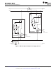
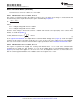
8.3.3 Inside the INA193-INA198
The INA193-INA198 devices use a new, unique internal circuit topology that provides common-mode range
extending from −16 to 80 V while operating from a single power supply. The common-mode rejection in a classic
instrumentation amplifier approach is limited by the requirement for accurate resistor matching. By converting the
induced input voltage to a current, the INA193-INA198 devices provide common-mode rejection that is no longer
a function of closely matched resistor values, providing the enhanced performance necessary for such a wide
common-mode range. A simplified diagram (shown in Figure 21) shows the basic circuit function. When the
common-mode voltage is positive, amplifier A2 is active.
12 Submit Documentation Feedback Copyright © 2004–2015, Texas Instruments Incorporated
Product Folder Links: INA193 INA194 INA195 INA196 INA197 INA198