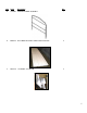
DOUBLE ENTRY 30ꞌ BLUE COVERED CART CORRAL (PART NUMBER 8030401) PACKING LIST AND ASSEMBLY INSTRUCTIONS 3125 Boschertown Road, St. Charles, MO 63301 (800) 455-3802 www.nationalcart.
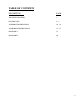
TABLE OF CONTENTS DESCRIPTION PAGE TOP LEVEL DRAWING 3 PACKING LIST 4-9 ASSEMBLY INSTRUCTIONS 10 - 16 ANCHORING INSTRUCTIONS 17 – 18 DIAGRAM A 19 DIAGRAM B 20 2
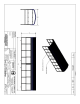
QTY PACKING LIST 1 Item Part # Description Qty. A 2030144 BASE ANGLE ASSEMBLY 4 B 3030420 RUB RAIL, 1/4X2X42.5" 16 C 3030416 HEADER HOOP, 105"X96.
Item Part # Description Qty. D 1030002 CENTER HEADER ASSEMBLY 1 E B000274 BLUE MAXI RIB STEEL SHEET 29GA 38.
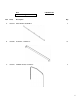
Item Part # Description Qty. G B000277 OUTSIDE ANGLE TRIM, BLUE 2 H B000971 POLYGAL PANEL 31.75" X 44" CLEAR I 3030425 H-CHANNEL,ALUMINUM 31.5” W/DRILLED HOLES 12 J 3030426 C-CHANNEL,ALUMINUM 31.
15' HARDWARE KITS: 2 Hardware of following kits: Qty. per kit Part # HEADER ASSY. HARDWARE KIT K HEX HEAD SCREW, 3/8-16 x 2-3/4" GR5 ZN 16 B000181 L FLAT WASHER, 3/8 x1 x 7/16” USS ZN 32 B000068 M SPLIT LOCK WASHER, 3/8" ZN 16 B000069 N HEX NUT 3/8-16 UNC GR5 ZN 16 B000057 RUB RAIL ASSY.
P BASE PLATE ASSY. HARDWARE KIT FLAT WASHER, 1/2 x1.38 x 9/16” USS ZN 16 B000075 Q J-BOLT, 1/2-13x8", (2” HOOK) 8 B000217 R HEX NUT, 1/2-13 UNC GR5 ZN 8 B000077 S LAG SCREW, 1/2 x 5.0” ZN 8 B000108 290 B000278 METAL ROOF HARDWARE KIT T TEK SCREW #12 x 1.
POLYGAL ATTACHMENT HARDWARE KIT V HEX HEAD SCREW 1/4-20 x 1.
DOUBLE-ENTRY COVERED CART CORRAL ASSEMBLY INSTRUCTIONS *LETTERS CORRESPOND TO ITEMS AS SHOWN IN PACKING LIST* Required Tools: 5/16” Nut driver 9/16” hand wrench Power drill 9/16” socket wrench Tin snips BASE ASSEMBLY 1. Select a flat, level area to place corral, away from but not limited to curbs & storm drains. 2. Lay out 2 base angles (A) approximately 9’ apart with sleeves facing to the inside. Lay out 2 more base angles (A), end-to-end, and parallel to the first two. HEADER ASSEMBLY 3.
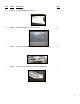
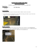
4. Place remaining headers (C) over sleeves at positions H1, H2, H3, H4, H6, H7, H8 & H9 (Diagram A) on base angles (A). Secure with components from header assembly hardware kit (K, L, M, N), do not tighten bolts. RUB RAIL ASSEMBLY 5. Place one rub rail (B) between 2 headers with flat side to the inside of the corral. At the entry points of the corral attach the end of the rub rail with; 3/8 x 2-3/4 HHCS, 3/8 flat washer, lock washer and hex nut (photo A).
METAL ROOF ASSEMBLY 7. Lay out edge of first maxi rib panel (E) at top of header (C) flush at location H1 but overhanging at location H5, with rib centered over peak. Take note that one side of the maxi rib panel (E) has a longer flange than the other side. The “shorter” side is the side that you want to end up as the exposed side of the maxi rib panel on the side of the unit. This will be the end that will go into the “J” channel in step 12. Secure with one #12 x 1.
12. Install one “J” channel (F) per 15’ section, repeat on other 15’ section, secure at locations H1 through H9, using #12 x 1” tek screws making sure that the screws are passing through the maxi rib panel (E), the “J” channel (F), and the header (C). Also, make sure that the maxi rib panel is inside the “J” channel. 13. Repeat step 12 for opposite side of corral. POLYGAL ASSEMBLY 14. A.
B. Making sure that the “H” channel is centered on the header put the second screw in the bottom hole. DO NOT OVER TIGHTEN C. Put “C” channel (J), for polygala, over one end of a polygal panel (H) and slide up through one end of the “H” channel and secure “C” channel on entry end header with tek screw through small (5/16”) hole in top of “C” channel. DO NOT OVER TIGHTEN D. Drill Through 5/16” hole and through the polygal panel using 5/16” hole in ”C” and “H” channels as a guide. E.
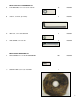
F. Secure polygal panels with the hardware provided F1 F2 (inside of unit) F3 G. There will be two “C” channels facing back to back on the header/sign assembly. At this point there will be 4 polygal panels up, all with a “C” channel on one end.
H. Slide the remaining polygal panels up through each side of the remaining “H” channels and secure with ¼”-20 x 1” HHCS. 15. Repeat step 14 for opposite side of corral. FACIA ASSEMBLY 16. Install fascia (G) to header (C) at location H1 (Diagram B). Cut center face in length of fascia (G) with tin snips. Align the cut with peak of header (C). Bend both sides of fascia (G) down to conform with shape of header (C). Secure lap joint at peak of header (C) with #12 x 1.0” tek screw in face.
ANCHORING CORRAL ASPHALT SURFACE (Using “J” Anchors) Required Tools: 9/16” hand wrench Power drill 9/16” socket wrench Pry bar 8” dia. Core drill (for anchoring) 1. Position cart corral in desired location. 2. Marks holes onto lot surface, at positions A1, A4, A5 & A8 (double entry cart corral) or A1 & A4 (single entry cart corral) on both sides of corral. (Diagram A) 3. Use pry bar to move unit at least 10” sideways. 4. Using a core drill, drill a 8” x 24” deep hole at each position.
CONCRETE SURFACE NOTE: Use ½” X 5 ½” wedge anchors (provided by others) when installing on a concrete surface. Required Tools: 9/16” hand wrench Power drill 9/16” socket wrench Pry bar Hammer 1/4” Twist & 8” dia. Core drill (for anchoring) 1. Position cart corral in desired location. 2. Mark holes onto lot surface, at positions A1 through A8 (double entry cart corral) or A1 through A4 (single entry cart corral) on both sides of cart corral. (Diagram A) 3. Use pry bar to move unit at least 10” sideways. 4.
DIAGRAM A 19