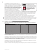
INSTALLER: LEAVE THIS MANUAL WITH THE APPLIANCE. CONSUMER: RETAIN THIS MANUAL FOR FUTURE REFERENCE. INSTALLATION AND OPERATING INSTRUCTIONS CERTIFIED UNDER CANADIAN AND AMERICAN NATIONAL STANDARDS: CSA 2.22, ANSI Z21.50 FOR VENTED GAS FIREPLACE. GT8N NATURAL GAS GT8P PROPANE CERTIFIED FOR CANADA AND UNITED STATES USING ANSI/CSA METHODS.
TABLE OF CONTENTS 1.0 2.0 3.0 INSTALLATION OVERVIEW INTRODUCTION 3 4 2.1 2.2 2.3 2.4 5 5 6 7 VENTING 3.1 3.2 3.3 3.4 4.0 5.0 6.0 7.0 10.0 11.0 12.0 13.0 14.0 VENTING LENGTHS AND COMPONENTS VENT TERMINAL CLEARANCES HORIZONTAL TERMINATION VERTICAL TERMINATION 8 9 10 11 12 INSTALLATION 13 4.1 4.2 4.3 4.4 4.4.1 4.4.2 4.4.3 4.5 4.
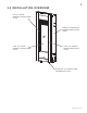
1.0 INSTALLATION OVERVIEW Door, see “DOOR REMOVAL / INSTALLATION” section. Cabinet, see “MOUNTING CABINET INSTALLATION” section. Glass, see “GLASS REMOVAL / INSTALLATION” section. Frame, see “FRAME / FRONT INSTALLATION” section. Rating plate, see “RATING PLATE INFORMATION” section. W415-0794 / B / 11.03.
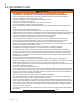
2.0 INTRODUCTION ! • • • • • • • • • • • • • • • • • • • • • • • • • • • • • WARNING THIS APPLIANCE IS HOT WHEN OPERATED AND CAN CAUSE SEVERE BURNS IF CONTACTED. ANY CHANGES TO THIS APPLIANCE OR IT’S CONTROLS CAN BE DANGEROUS AND IS PROHIBITED. Do not operate appliance before reading and understanding operating instructions. Failure to operate appliance according to operating instructions could cause fire or injury. Risk of fire or asphyxiation do not operate appliance with fixed glass removed.
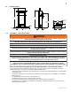
2.1 DIMENSIONS 1 /4 37 /4 3 43 / 3 4 3" DIA. 5" DIA. ELECTRICAL ACCESS 2.2 GAS LINE ACCESS 2 GENERAL INSTRUCTIONS ! WARNING ALWAYS LIGHT THE PILOT WHETHER FOR THE FIRST TIME OR IF THE GAS SUPPLY HAS RAN OUT, WITH THE GLASS DOOR OPENED OR REMOVED. PROVIDE ADEQUATE CLEARANCE FOR SERVICING AND OPERATING THE APPLIANCE. PROVIDE ADEQUATE VENTILATION. NEVER OBSTRUCT THE FRONT OPENING OF THE APPLIANCE.
The installation must conform with local codes or, in absence of local codes, the National Gas and Propane Installation Code CSA B149.1 in Canada, or the National Fuel Gas Code, ANSI Z223.1 / NFPA 54 in the United States. Suitable for mobile home installation if installed in accordance with the current standard CAN/CSA Z240MH Series, for gas equipped mobile homes, in Canada or ANSI Z223.1 and NFPA 54 in the United States. www.nficertified.
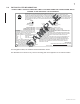
RATING PLATE INFORMATION RATING LABEL LOCATION: THE RATING LABEL IS LOCATED UNDER THE CONTROL PANEL AND IS CHAINED TO THE APPLIANCE. DO NOT REMOVE. M P LE CERTIFIED UNDER : CSA 2.22b-2009, ANSI 21.50b-2009 VENTED GAS FIREPLACE DIRECT VENT GAS FIREPLACE. APPROVED FOR BEDROOM, BATHROOM AND BED SITTIN SITTING ROOM INSTALLATION. SUITABLE FOR MOBILE HOME INSTALLATION IF INSTALLED IN ACCORDANCE CURRENT STANDARD CAN/CSA DANCE ANCE WITH THE CUR Z240MH SERIES GAS EQUIPPED MOBILE HOMES.
3.0 VENTING ! WARNING RISK OF FIRE, MAINTAIN SPECIFIED AIR SPACE CLEARANCES TO VENT PIPE AND APPLIANCE. IF VENTING IS INCLUDED WITH SPACERS THE VENT SYSTEM MUST BE SUPPORTED EVERY 3 FEET FOR BOTH VERTICAL AND HORIZONTAL RUNS. USE SUPPORTS OR EQUIVALENT NON-COMBUSTIBLE STRAPPING TO MAINTAIN THE REQUIRED CLEARANCE FROM COMBUSTIBLES. USE WOLF STEEL LTD.
3.1 VENTING LENGTHS AND COMPONENTS The vent connection to the appliance can be viewed by removing the baffle from the top, inside of the firebox. Use only Wolf Steel venting components. Minimum and maximum vent lengths, for both horizontal and vertical installations, and air terminal locations for either system are set out in this manual and must be adhered to. Use only Wolf Steel Ltd. flexible vent components with the Wolf Steel Ltd. GD179 termination kit.
3.2 VENT TERMINAL CLEARANCES COVERED BALCONY APPLICATIONS DE O N H C F Q M H A B B J K O G R L INSTALLATIONS CANADA M G Q MIN = 3 feet R MAX = 2 x Q ACTUAL R MAX feet P U.S.A. A 12” 12” Clearance above grade, veranda porch, deck or balcony. B 12” Δ 9” Δ Clearance to windows or doors that open. C 12” * 12” * Clearance to permanently closed windows.
3.
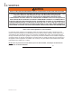
3.4 VERTICAL TERMINATION MIN MAX Allowable 3” vent connections (excluding appliance and air terminal connections) N/A 2 Rise per foot (recommended) 1/4” N/A Rise per foot (allowable) 0” N/A Vertical run (when not venting horizontally) 24” 19 1/2 FT Horizontal run 4” 5 FT See graph to determine the required vertical rise VT for the required horizontal rise HT. 20 19.5 18 16 15 14 12 REQUIRED VERTICAL RISE IN FEET (VT) 10 8 24” MIN. 6 4 19 1/2 FT MAX. MINIMUM 4” VERITICAL MIN. 2 1.
4.0 INSTALLATION ! WARNING FOR SAFE AND PROPER OPERATION OF THE APPLIANCE, FOLLOW THE VENTING INSTRUCTIONS EXACTLY. ALL INNER EXHAUST AND OUTER INTAKE VENT PIPE JOINTS MAY BE SEALED USING EITHER RED RTV HIGH TEMP SILICONE SEALANT W573-0002 (NOT SUPPLIED) OR BLACK HIGH TEMP MILL PAC W573-0007 (NOT SUPPLIED) WITH THE EXCEPTION OF THE APPLIANCE EXHAUST FLUE COLLAR WHICH MUST BE SEALED USING MILL PAC.
4.2 HORIZONTAL INSTALLATION ! WARNING THE FIRESTOP ASSEMBLY MUST BE INSTALLED WITH THE VENT SHIELD TO THE TOP. TERMINALS MUST NOT BE RECESSED INTO A WALL OR SIDING MORE THAN THE DEPTH OF THE RETURN FLANGE OF THE MOUNTING PLATE. This application occurs when venting through an exterior wall. Having determined the correct height for the air terminal VENT location, cut and frame a hole in the exterior wall as SHIELD illustrated to accommodate the firestop assembly.
4.4 USING FLEXIBLE VENT COMPONENTS ! WARNING DO NOT ALLOW THE INNER FLEX PIPE TO BUNCH UP ON HORIZONTAL OR VERTICAL RUNS AND ELBOWS. KEEP IT PULLED TIGHT. SPACERS ARE ATTACHED TO THE INNER FLEX PIPE AT PREDETERMINED INTERVALS TO MAINTAIN AN EVEN AIR GAP TO THE OUTER FLEX PIPE. THIS GAP IS REQUIRED FOR SAFE OPERATION. A SPACER IS REQUIRED AT THE START, MIDDLE AND END OF EACH ELBOW TO ENSURE THIS GAP IS MAINTAINED. THESE SPACERS MUST NOT BE REMOVED.
4.4.2 VERTICAL AIR TERMINAL INSTALLATION ! WARNING MAINTAIN A MINIMUM 2” SPACE BETWEEN THE AIR INLET BASE AND THE STORM COLLAR. A. Fasten the roof support to the roof using the screws provided. The roof support is optional. In this case the venting is to be adequately supported using either an alternate method suitable to the authority having jurisdiction or the optional roof support. B. Stretch the inner flex pipe to the required length.
4.4.3 APPLIANCE VENT CONNECTION A. B. Install the inner flex pipe to the fireplace. Secure with 3 screws and flat washers. Seal the joint and screw holes using the high temperature sealant W573-0007 (not supplied). Install the outer flex pipe to the fireplace. Attach and seal the joints using the high temperature sealant W573-0002 (not supplied). 1 1/2” OVERLAP HIGH TEMPERATURE SEALANT SCREWS 28.4 4.5 GAS INSTALLATION ! WARNING RISK OF FIRE, EXPLOSION OR ASPHYXIATION.
4.6 MOBILE HOME This appliance is certified to be installed as an OEM (Original Equipment Manufacturer) installation in a manufactured home or mobile home and must be installed in accordance with the manufacturer’s instructions and the Manufactured Home Construction and Safety Standard, Title 24 CFR, Part 3280, or, when such a standard is not applicable, the Standard for Manufactured Home Installations, ANSI/NCSBCS A225.
5.0 FRAMING ! WARNING RISK OF FIRE! IN ORDER TO AVOID THE POSSIBILITY OF EXPOSED INSULATION OR VAPOUR BARRIER COMING IN CONTACT WITH THE APPLIANCE BODY, IT IS RECOMMENDED THAT THE WALLS OF THE APPLIANCE ENCLOSURE BE “FINISHED” (IE: DRYWALL / SHEETROCK), AS YOU WOULD FINISH ANY OTHER OUTSIDE WALL OF A HOME. THIS WILL ENSURE THAT CLEARANCE TO COMBUSTIBLES IS MAINTAINED WITHIN THE CAVITY. DO NOT NOTCH THE FRAMING AROUND THE APPLIANCE STAND-OFFS.
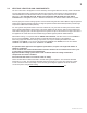
5.1 MINIMUM CLEARANCE TO COMBUSTIBLES Minimum clearance to combustible construction from appliance and vent surfaces: Appliance framing: - 6” to top - 0” to stand-offs (Rear and sides) Vent pipe*: - 2” top - 1” sides and bottom Recessed depth: - 7” * HORIZONTAL VENT SECTIONS: A minimum clearance of 1” at the bottom and sides and 2” at the top of the vent pipe in all horizontal runs to combustibles is required. Use firestop spacer W010-1961 (supplied).
MINIMUM ENCLOSURE CLEARANCES INTERIOR BUILT-OUT OUTSIDE CHASE 21 1/4" 7" /12" 14 1/2" 14 EXTERIOR CHASE 30 ” 5.2 21 INSIDE CHASE 7" 2" 4" 14 1/2" SIDE WALL 2" PROTRUSION 4" 6" 44 1/4" 34 7/8" TM TORCH TM TORCH 11 5/8" 7" 14 1/2" 1 FRAMING OPENING DIMENSIONS 2 3 INSTALLATION FINISHING OPENING DIMENSIONS NOTE: Finished opening is smaller than the framed opening. W415-0794 / B / 11.03.
5.3 NAILING TAB INSTALLATION Attach the 4 nailing tabs supplied to the sides of the outer shell as illustrated using the 8 self-tapping screws included in the manual baggie. 5.4 STAND-OFF ASSEMBLY 1 W415-0794 / B / 11.03.
6.0 FINISHING ! WARNING RISK OF FIRE! NEVER OBSTRUCT THE FRONT OPENING OF THE APPLIANCE. THE FRONT OF THE APPLIANCE MUST BE FINISHED WITH ANY NON-COMBUSTIBLE MATERIALS SUCH AS BRICK, MARBLE, GRANITE, ETC., PROVIDED THAT THESE MATERIALS DO NOT GO BELOW THE SPECIFIED DIMENSION AS ILLUSTRATED. DO NOT STRIKE, SLAM OR SCRATCH GLASS. DO NOT OPERATE APPLIANCE WITH GLASS REMOVED, CRACKED, BROKEN OR SCRATCHED. FACING AND/OR FINISHING MATERIAL MUST NEVER OVERHANG INTO THE APPLIANCE OPENING. 72.1A 6.
B. Remove the template. Depending on the surface and fasteners, drill the appropriate holes. Hold the Torch up, aligning the mounting brackets to the mounting holes. Secure the Torch to the wall using the appropriate fasteners. NOTE: The Torch has been designed to have a 1/2” clearance between the rear outer panel and the mounting surface. C. Start the fasteners into each of the six remaining mounting holes.
6.2 DOOR REMOVAL ! WARNING GLASS MAY BE HOT, DO NOT TOUCH GLASS UNTIL COOLED. THE DOOR LATCHES ARE PART OF A SAFETY SYSTEM AND MUST BE PROPERLY ENGAGED. DO NOT OPERATE THE APPLIANCE WITH LATCHES DISENGAGED. FACING AND/OR FINISHING MATERIALS MUST NOT INTERFERE WITH AIR FLOW THROUGH AIR OPENINGS, LOUVRES OPENINGS, OPERATION OF LOUVRES OR DOORS OR ACCESS FOR SERVICE. OBSERVE ALL CLEARANCES WHEN APPLYING COMBUSTIBLE MATERIALS.
6.3 FRAME/FRONT INSTALLATION A. B. Align the two holes in the upper portion of the hinge on the control door to those in the bottom trim bracket, secure using two of the #8 x 1/2” hex head screws supplied. W385-0479 W385-047 9 Install the top trim bracket to the firebox using the three #9 - 14 x 1/2” hex head screws supplied in the CONTROL DOOR manual baggie. BOTTOM TRIM BRACKET C.
6.4 ACCENT GLASS INSTALLATION Carefully sprinkle the accent glass onto the glass support evenly. Ensure no glass falls into the burner area. If this happens, insert a clean bag into your vacuum cleaner and vacuum out the accent glass. Replacement accent glass can be purchased from Wolf Steel Ltd. ACCENT GLASS BURNER GLASS SUPPORT B. Remove the frame from the appliance by removing the 2 black securing screws from the top, and the 2 silver hex head securing screws from the bottom. C.
7.0 ELECTRICAL INFORMATION ! WARNING RISK OF ELECTRIC SHOCK! CONTROL AND VALVE OPERATE WITH 110V. DO NOT USE THE APPLIANCE IF ANY PART HAS BEEN UNDER WATER. CALL A QUALIFIED SERVICE TECHNICIAN IMMEDIATELY TO HAVE THE APPLIANCE INSPECTED FOR DAMAGE TO THE ELECTRICAL CIRCUIT. HARD WIRING CONNECTION It is necessary to hard wire this appliance. Permanently framing the appliance with an enclosure, requires the appliance junction box to be hard wired.
8.0 OPERATION ! WARNING IF YOU DO NOT FOLLOW THESE INSTRUCTIONS EXACTLY, A FIRE OR EXPLOSION MAY RESULT CAUSING PROPERTY DAMAGE, PERSONAL INJURY OR LOSS OF LIFE. Ensure that a continuous gas flow is at the burner before installing the door. When lit for the first time, the fireplace will emit an odor for a few hours. This is a normal temporary condition caused by the “burn-in” of paints and lubricants used in the manufacturing process and will not occur again.
9.0 ADJUSTMENTS 9.1 GAS PRESSURE ADJUSTMENT Outlet pressure can be adjusted if not measuring 3.5” W.C. (NG) or 10.0” W.C. (LP). 9.2 A. Pressure can be checked by removing cap (A) using a 3/16 Allen key and replacing it with a 1/8 NPT barb fitting. B. Place pressure gauge tube over the fitting. C. Pressure can be adjusted by removing cap (B) using a flat screwdriver, and adjusting the nylon plug with the same screw driver. Turning the plug in (clockwise) will increase the pressure.
10.0 MAINTENANCE MAINTENANCE ! WARNING MAINTENANCE TURN OFF THE GAS AND ELECTRICAL POWER BEFORE SERVICING THE APPLIANCE. APPLIANCE MAY BE HOT, DO NOT SERVICE UNTIL APPLIANCE HAS COOLED. DO NOT USE ABRASIVE CLEANERS. CAUTION: Label all wires prior to disconnection when servicing controls. Wiring errors can cause improper and dangerous operation. Verify proper operation after servicing.
10.2 DOOR GLASS REPLACEMENT ! WARNING DO NOT USE SUBSTITUTE MATERIALS. GLASS MAY BE HOT, DO NOT TOUCH GLASS UNTIL COOLED. CARE MUST BE TAKEN WHEN REMOVING AND DISPOSING OF ANY BROKEN DOOR GLASS OR DAMAGED COMPONENTS. BE SURE TO VACUUM UP ANY BROKEN GLASS FROM INSIDE THE APPLIANCE BEFORE OPERATION. DO NOT STRIKE, SLAM OR SCRATCH GLASS. DO NOT OPERATE APPLIANCE WITH GLASS REMOVED, CRACKED, BROKEN OR SCRATCHED. 56.2 Having removed the door, lay on a smooth flat surface, face down.
11.0 REPLACEMENTS Contact your dealer or the factory for questions concerning prices and policies on replacement parts. Normally all parts can be ordered through your Authorized dealer / distributor. FOR WARRANTY REPLACEMENT PARTS, A PHOTOCOPY OF THE ORIGINAL INVOICE WILL BE REQUIRED TO HONOUR THE CLAIM.
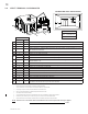
TERMINAL KITS REF NO. PART NO. DESCRIPTION GD178 (WALL TERMINAL KIT) 28* W010-1744 12” FLEXIBLE VENT ASSEMBLY 29 W670-0013 3”/5” HORIZONTAL TERMINAL GD179 (TERMINAL ONLY) 29 W670-0013 3”/5” HORIZONTAL TERMINAL ROOF TERMINAL KITS REF NO. PART NO.
7 6 8 11 12 13 16 1 4 22 19 20 15 W415-0794 / B / 11.03.
12.0 TROUBLE SHOOTING ! WARNING ALWAYS LIGHT THE PILOT WHETHER FOR THE FIRST TIME OR IF THE GAS SUPPLY HAS RAN OUT, WITH THE GLASS DOOR OPEN OR REMOVED. TURN OFF THE GAS AND ELECTRICAL POWER BEFORE SERVICING THE APPLIANCE. APPLIANCE MAY BE HOT, DO NOT SERVICE UNTIL APPLIANCE HAS COOLED. DO NOT USE ABRASIVE CLEANERS. SYMPTOM PROBLEM TEST SOLUTION Electrode sparks, burner ignites, electrode continues to spark for complete 7 seconds, burner shuts down.
SYMPTOM No gas to the main burner; switch is on. PROBLEM TEST SOLUTION Switch is defective. - Connect a jumper wire across the wall switch terminals; if main burner lights, replace switch / thermostat. Burner orifice is blocked. - Remove stoppage in orifice. Control valve faulty. - Replace. Faulty valve. - Replace. Burner will not light, ignitor sparks. No gas at the burner. - Check that the manual valve is turned on. Replace the valve. Out of propane gas. - Fill the tank.
13.0 WARRANTY NAPOLEON® products are manufactured under the strict Standard of the world recognized ISO 9001 : 2008 Quality Assurance Certificate. NAPOLEON® products are designed with superior components and materials assembled by trained craftsmen who take great pride in their work. The burner and valve assembly are leak and test-fired at a quality test station.
14.0 SERVICE HISTORY 43.1 W415-0794 / B / 11.03.
15.0 NOTES 44.1 W415-0794 / B / 11.03.