
Full Product Manual
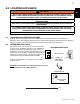

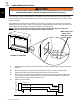

A. Remove the securing screw from the electrical cover plate, located on the right hand side of the
fireplace.
B. Add an electrical box connector and feed the supply wires through the 7/8" (22mm) hole.
C. Separate the black, white and green wires that have the wire nuts on them.
D. Remove the wire nuts and secure the black wire (power L1) to the black (power L1) lead of the
power supply. Connect the white wire from the unit to the white (neutral) wire from the power
supply. Connect the green wire to the ground wire.
E. Resecure the cover plate.
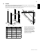
BLACK
WHITE
BLACK
WHITE
GREEN
GREEN
GROUND
BLACK
BLACK
BLACK
WHITE
WHITE
WIRE NUT
WALL
SWITCH
POWER
SUPPLY
MARRET
RED
RED
RED
RED
GREEN
GREEN
THERMOSTAT
(L1)
(N)
(G)
WIRE NUT
(L1)
(N)
(L1)
(N)
EN
W415-1454 / F / 03.16.17
10
GREEN
BLACK
WHITE
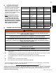
HARD WIRING CONNECTION
If it is necessary to hard wire this appliance, a qualified electrician must remove the cord connection, and
wire the appliance directly to the household wiring. The wire and power supply breaker must rated for 120V
minimum 15 Amps.
This appliance must be electrically connected and grounded in accordance with local codes, if hard wired.
In the absence of local codes, use the current CSA C22.1 CANADIAN ELECTRICAL CODE in Canada or the
current ANSI/NFPA 70 NATIONAL ELECTRICAL CODE in the United States.
!
WARNING
TURN OFF THE APPLIANCE COMPLETELY AND LET COOL BEFORE SERVICING. ONLY A QUALIFIED
SERVICE PERSON SHOULD SERVICE AND REPAIR THIS ELECTRIC APPLIANCE.
GREEN
BLACK
WHITE
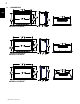
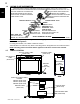
NOTE: There are 3 wires from the fireplace junction; white (neutral), black (power L1) and green
(ground) that connect to 120V power supply (breaker panel), see below.
White, Green and
Black wires:
Connect to 120V
power supply.
3.3.1 HARD WIRING INSTALLATION
* NEFB29H ILLUSTRATED