INSTALLER: LEAVE THIS MANUAL WITH THE APPLIANCE. CONSUMER: RETAIN THIS MANUAL FOR FUTURE REFERENCE. INSTALLATION AND OPERATING INSTRUCTIONS CERTIFIED UNDER CANADIAN AND AMERICAN NATIONAL STANDARDS: CR97-003, CAN1-2.21-M85, IAS U.S. 4-96. PATIOFLAME OUTDOOR GAS FIREPLACE GPFN NATURAL GAS GPFP PROPANE CERTIFIED FOR CANADA AND UNITED STATES USING ANSI/CSA METHODS.
TABLE OF CONTENTS 1.0 INTRODUCTION 3 2.0 SPECIFICATIONS 6 3.0 INSTALLATION 7 4.0 FINISHING 9 5.0 6.0 OPERATION MAINTENANCE 11 12 7.0 8.0 REPLACEMENTS SERVICE HISTORY 13 15 1.1 1.2 WARRANTY GENERAL INFORMATION 2.1 DIMENSIONS 3.1 3.2 3.3 3.4 NATURAL GAS LP (PROPANE) GAS ENCLOSURES FOR LP GAS SUPPLY SYSTEMS CYLINDER RETAINING BRACKET 4.1 4.2 4.3 LOG PLACEMENT / AGGREGATE OPTIONAL MKR ROCK INSTALLATION GLASS MEDIA INSTALLATION 6.1 6.
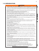
1.0 INTRODUCTION ! • • • • • • • • • • • • • • • • • • • • • • • • • • • • WARNING THIS APPLIANCE IS HOT WHEN OPERATED AND CAN CAUSE SEVERE BURNS IF CONTACTED. Installation and repair should be done by a qualified service person. The appliance should be inspected before use and at least annually by a qualified service person. More frequent cleaning may be required as necessary. It is imperative the control compartment, burners and circulating air passageways of the appliance be kept clean.
1.1 WARRANTY NAPOLEON® gas appliances are manufactured under the strict Standard of the world recognized ISO 9001 : 2008 Quality Assurance Certificate. NAPOLEON® products are designed with superior components and materials, assembled by trained craftsmen who take great pride in their work. The burner and valve assembly are leak and test-fired at a quality test station.
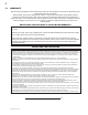
1.2 GENERAL INFORMATION This appliance should be installed and serviced by a qualified installer to conform with local codes. Installation practices vary from region to region and it is important to know the specifics that apply to your area, for example: in Massachusetts State: • The appliance off valve must be a “T” handle gas cock. • The flexible connector must not be longer than 36 inches.
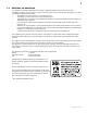
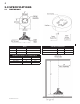
2.0 SPECIFICATIONS 2.1 DIMENSIONS GAS INLET PRESSURES INPUT MODEL FUEL MAX. INPUT Btu/Hr GPFN Natural Gas 60, 000 GPFP Propane Gas 60, 000 MINIMUM CLEARANCE TO COMBUSTIBLES INCHES MM Floor *0 *0 Side Walls 24 610 Top of unit to ceiling 72 1830 W415-0638 / D / 03.14.12 NATURAL PROPANE Minimum Inlet Pressure 4.5" w.c. 11.0" w.c. Maximum Inlet Pressure 14.0" w.c. 14.0" w.c.
3.0 INSTALLATION ! WARNING WHEN THE APPLIANCE IS BEING USED WITH THE OPTIONAL TRIPOD, IT MUST BE SITUATED ON A NON-COMBUSTIBLE SURFACE, NOR CAN IT BE LOCATED BELOW A COMBUSTIBLE OVERHANG. ! WARNING The log set and the burner assembly are shipped together. Remove the gas log set and burner assembly and check for damage. DO NOT install damaged components. The logs are fragile use care when handling. Place the appliance on a level/secure surface in desired location.
3.3 ENCLOSURES FOR LP GAS SUPPLY SYSTEMS ! WARNING DURING THE INITIAL PURGING AND SUBSEQUENT LIGHTINGS, NEVER ALLOW GAS VALVE TO REMAIN IN THE "OPEN" POSITION WITHOUT FIRST PLACING AND IGNITING THE FIRESTARTER. WARNING If you build an enclosure for an LP gas cylinder, follow these recommended specifications. You must also follow local codes. ! Enclosures for LP gas supply cylinders shall be ventilated by openings at the level of the cylinder valve and at floor level.
4.0 FINISHING 4.1 LOG PLACEMENT / AGGREGATE #1 BASE LOG 4.1.1 Set base log onto burner ensuring stud and bracket fit into hole and notch. Base log should sit flat on "Patioflame" base. 4.1.2 #2 4.1.3 Place pocket on log #2 onto the locator on the base log. #3 4.1.4 Place log #4 into notch on base and pocket on log #3. Hook log #3 into notch on base log. AGGREGATE #4 4.1.5 Place "Y" end of log #1 into "Y" notch on the base log. 4.1.6 The appliance is supplied with 3lbs of lava rock.
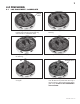
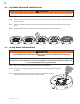
4.2 OPTIONAL MKR ROCK INSTALLATION ! WARNING REAL ROCKS MUST NOT BE USED IN THIS APPLIANCE. HEAT WILL CAUSE THEM TO EXPLODE. 4.2.1 Remove the refractory logs and lava rocks from your appliance. 4.2.2 Place the 4 notched rocks and 2 clusters on the edge of the burner pan as shown, making sure not to cover any ports. 4.2.3 Place the remaining refractory rocks on and around the burner as desired. (There are not set locations). 4.2.
5.0 OPERATION ! WARNING IF YOU DO NOT FOLLOW THESE INSTRUCTIONS EXACTLY, A FIRE OR EXPLOSION MAY RESULT CAUSING PROPERTY DAMAGE, PERSONAL INJURY OR LOSS OF LIFE. ALWAYS LIGHT THE PILOT WHETHER FOR THE FIRST TIME OR IF THE GAS SUPPLY HAS RUN OUT WITH THE GLASS DOOR OPENED OR REMOVED. Upon completing the gas line connection, a small amount of air will be in the lines. When first lighting the burner, it will take a few seconds for the lines to purge themselves of this air.
6.0 MAINTENANCE 6.0.1 The appliance should be inspected before initial use and inspected and cleaned at least annually by a qualified field service person. 6.0.2 Tampering is DANGEROUS and voids all warranties. Any component that is found to be faulty, must be replaced with an approved component. 6.0.3 To obtain proper operation, it is imperative that the burner flame characteristics are steady, not lifting or floating. Check the burner flame patterns with the figure below. 6.0.
7.0 REPLACEMENTS Contact your dealer or the factory for questions concerning prices and policies on replacement parts. Normally all parts can be ordered through your Authorized dealer / distributor. FOR WARRANTY REPLACEMENT PARTS, A PHOTOCOPY OF THE ORIGINAL INVOICE WILL BE REQUIRED TO HONOUR THE CLAIM.
3 16 13 4 5 6 14 12 9 8 2 10 11 7 W415-0638 / D / 03.14.
8.0 SERVICE HISTORY 43.1 W415-0638 / D / 03.14.
9.0 NOTES 44.1 W415-0638 / D / 03.14.
Date Détaillant H Historique Historique d’entretien d'entretien deWolf l'appareil Steel Problèmes particuliers 22 16 Travail effectué Cet appareil doit être entretenu annuellement selon son usage. Nom du technicien W415-0638 / C / 03.14.12 W415-0676 / 04.30.08 43.1 8.
15 3 16 13 4 5 6 14 12 9 8 2 10 11 7 1 W415-0638 / C / 03.14.
14 7.0 RECHANGES Contactez votre détaillant pour les questions concernant les prix et la disponibilité des pièces de rechange. Normalement, toutes les pièces peuvent être commandées chez votre détaillant autorisé. POUR UN REMPLACEMENT DE PIÈCE SOUS GARANTIE, UNE PHOTOCOPIE DE LA FACTURE ORIGINALE SERA REQUISE AFIN DE POUVOIR HONORER LA DEMANDE.
6.2 13 NETTOYAGE DE L’ACIER INOXYDABLE L’acier inoxydable a tendance à s’oxyder ou à tacher en présence de chlorures et de sulfures, particulièrement dans les zones côtières ainsi que dans les environnements chauds et humides tels que les piscines et les spas. Ces taches, considérées parfois comme de la rouille, peuvent être évitées et éliminées facilement.
12 6.0 ENTRETIEN 6.0.1 Cet appareil devrait être inspecté avant la première utilisation, et inspecté et nettoyé au moins une fois l'an par un technicien de service qualifié. 6.0.2 Toutes altérations apportées à l'appareil sont considérées comme DANGEREUSES et annulent toutes les garanties. Tout composant défectueux doit être remplacé par un composant recommandé par le fabricant. 6.0.
11 5.0 FONCTIONNEMENT ! AVERTISSEMENT SI CES INSTRUCTIONS NE SONT PAS SUIVIES À LA LETTRE, UN FEU OU UNE EXPLOSION POURRAIENT S’ENSUIVRE, CAUSANT DES DOMMAGES MATÉRIELS, DES BLESSURES CORPORELLES OU DES PERTES DE VIE. ! AVERTISSEMENT ALLUMEZ TOUJOURS LA VEILLEUSE, QUE CE SOIT POUR LA PREMIÈRE FOIS OU LORSQUE L’APPROVISIONNEMENT EN GAZ EST ÉPUISÉ, AVEC LA PORTE VITRÉE OUVERTE OU RETIRÉE.
10 4.2 INSTALLATION DES ROCHES MKR ! AVERTISSEMENT NE PAS UTILISER DE VRAIES ROCHES SUR CET APPAREIL. LA CHALEUR LES FERA EXPLOSER. 4.2.1 Enlevez les bûches réfractaires et les pierres de lave de votre appareil. ! AVERTISSEMENT 4.2.2 Placez les quatre roches encochées et deux amas de roches sur le pourtour du brûleur à plateau tel qu’illustré, en vous assurant de ne pas couvrir les orifices du brûleur. 4.2.3 Placez les autres roches sur et autour du brûleur comme vous désirez.
9 4.0 FINITIONS 4.1 DISPOSITION DES BÛCHES/GRANULES BÛCHE DE BASE 4.1.1 Placez la bûche de base sur le brûleur en vous assurant que la tige et le support s'insèrent dans le trou et l'encoche. La bûche de base doit reposer à plat sur la base de l'appareil. #1 4.1.2 Placez l'extrémité en « Y » de la bûche #1 dans l'encoche en « Y » sur la bûche de base. #2 #3 4.1.3 Placez la cavité de la bûche #2 sur la tige de positionnement de la bûche de base. 4.1.
8 3.3 ENCLOS POUR LES SYSTÈMES D'ALIMENTATION AU PROPANE ! AVERTISSEMENT LORS DE LA PREMIÈRE PURGE ET LORS DES ALLUMAGES SUBSÉQUENTS, NE LAISSEZ JAMAIS LA SOUPAPEDE L'APPAREIL EN POSITION « OUVERTE » SANS AVOIR PRÉALABLEMENT PLACÉ ET ALLUMÉ L'ALLUME-FEU. ! AVERTISSEMENT Si vous désirez fabriquer un enclos pour une bonbonne de propane, suivez les spécifications suivantes. Vous devez également vous conformer aux codes locaux.
3.0 INSTALLATION ! 7 AVERTISSEMENT LORSQUE L'APPAREIL EST UTILISÉ AVEC LE TRÉPIED OPTIONNEL, IL DOIT ÊTRE SITUÉ SUR UNE SURFACE NON-COMBUSTIBLE, NE PEUT PAS NON SITUÉ SOUS UN SURPLOMB COMBUSTIBLE. AVERTISSEMENT L'ensemble de bûches et le brûleur sont expédiés ensemble. Retirez l'ensemble de bûches à gaz et le brûleur, et vérifiez qu'ils ne sont pas endommagés. N'INSTALLEZ PAS de composants qui sont endommagés. Les bûches étant fragiles, vous devez les manipuler avec grand soin.
6 2.0 SPÉCIFICATIONS 2.1 DIMENSIONS Brûleur Anneau extérieur Anneau extérieur Gaz naturel GPFN COMBUSTIBLE MODÈLE Tuyau/régulateur pour le propane NATUREL DÉBIT MAX. Btu/h 60 000 60 000 POUCES 24 Murs latéraux *0 Plancher Tuyau pour le gaz naturel (non fourni) PRESSIONS D'ALIMENTATION EN GAZ DÉBIT Propane GPFP Pression d'alimentation minimale Pression d'alimentation maximale 4,5" c.e. 14,0" c.e. PROPANE 11,0" c.e. 14,0" c.e.
1.2 5 INFORMATION GÉNÉRALE Cet appareil devrait être installé et entretenu par un installateur qualifié en se conformant aux codes locaux. Les pratiques d’installation peuvent varier d’une région à l’autre. Il est donc important de connaître les normes spécifiques qui s’appliquent à votre région. Par exemple dans l’État du Massachusetts : • La soupape d'arrêt doit être un robinet à gaz avec une poignée en T. • Le raccord flexible ne doit pas mesurer plus que 36 pouces.
4 1.1 GARANTIE Les appareils au gaz NAPOLÉON® sont fabriqués conformément aux normes strictes du certificat d’assurance de qualité mondialement reconnu ISO 9001 : 2008. Les produits NAPOLÉON® sont conçus avec des composants et des matériaux de qualité supérieure, assemblés par des artisans qualifiés qui sont fiers de leur travail. Le brûleur et le montage de la soupape subissent un test de détection de fuites et d'allumage à une station de test de qualité.
1.0 INTRODUCTION ! • • • • • • • • • • • • • • • • • • • • • • • • • • • • 3 AVERTISSEMENT CET APPAREIL EST CHAUD LORSQU’IL FONCTIONNE ET PEUT CAUSER DE GRAVES BRÛLURES EN CAS DE CONTACT. L’installation et les réparations doivent être effectuées par un technicien de service qualifié. Cet appareil doit être inspecté avant la première utilisation et au moins une fois l’an par un technicien de service qualifié. Un entretien plus fréquent pourrait être nécessaire.
2 TABLE DES MATIÈRES RECHANGES HISTORIQUE D'ENTRETIEN NOTES 7.0 8.0 9.0 FONCTIONNEMENT ENTRETIEN 5.0 6.0 FINITIONS 4.0 INSTALLATION 3.0 SPÉCIFICATIONS 2.0 INTRODUCTION 1.0 INSTALLATION À HAUTE ALTITUDE NETTOYAGE DE L’ACIER INOXYDABLE 6.1 6.2 DISPOSITION DES BÛCHES/GRANULES INSTALLATION DES ROCHES MKR INSTALLATION DES BRAISES VITRIFIÉES 4.1 4.2 4.3 GAZ NATUREL PROPANE ENCLOS POUR LES SYSTÈMES D'ALIMENTATION AU PROPANE PATTE DE FIXATION DU RÉSERVOIR 3.1 3.2 3.3 3.
! 1 INSTALLATEUR : LAISSEZ CE MANUEL AVEC L’APPAREIL. PROPRIÉTAIRE : CONSERVEZ CE MANUEL POUR CONSULTATION ULTÉRIEURE. INSTRUCTIONS D’INSTALLATION ET D’OPÉRATION HOMOLOGUÉ SELON LES NORMES NATIONALES CANADIENNES ET AMÉRICAINES, CR97-003, CAN1-2.21-M85, IAS U.S. 4-96. PATIOFLAME FOYERS EXTÉRIEURS AU GAZ GPFN GAZ NATUREL GPFP AVERTISSEMENT PROPANE CERTIFIÉ POUR LE CANADA ET LES ÉTATS-UNIS SELON LES MÉTHODES ANSI/CSA.