INSTALLER: THESE INSTRUCTIONS MUST BE CONVEYED TO AND REMAIN WITH THE HOMEOWNER. INSTALLATION AND OPERATION INSTRUCTIONS CERTIFIED UNDER CANADIAN AND AMERICAN NATIONAL STANDARDS: CSA 2.33, ANSI Z21.88 FOR VENTED GAS FIREPLACE HEATERS. GD82NT-T NATURAL GAS GD82PT-T PROPANE CERTIFIED FOR CANADA AND UNITED STATES USING ANSI/CSA METHODS.
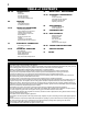
TABLE of CONTENTS PG 2-5 INTRODUCTION Warranty Dimensions General Instructions General Information Care of Glass & Plated Parts 5-9 15 Time Out Fireplace Operation Hand Held Remote Operation Dip Switch Number Chart Operating Instructions 24 25 CONVERSION KIT 26-27 REPLACEMENTS Replacement Parts Flexible Vent Kits Terminal Kits Roof Terminal Kits Accessories Replacement Parts Diagram ELECTRICAL CONNECTION Hard Wiring Connections ADJUSTMENTS Pilot Burner Adjustment Venturi Adjustment INSTALLATION/
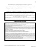
NAPOLEON® products are manufactured under the strict Standard of the world recognized ISO 9001 : 2000 Quality Assurance Certificate. NAPOLEON® products are designed with superior components and materials, assembled by trained craftsmen who take great pride in their work. The burner and valve assembly are leak and test-fired at a quality test station.
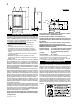
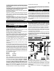
FIGURE 1 58" 46" 17 3/4" 37 /8" 5 4" DIA. 7" DIA. 1 21" 22 /8" 5" 2" 24" 28" 7 8 7/8" GENERAL INSTRUCTIONS 13 7/8" /8" 14" 28" Under extreme vent configurations, allow several minutes (5-15) for the flame to stabilize after ignition. THIS GAS FIREPLACE SHOULD BE INSTALLED AND SERVICED BY A QUALIFIED INSTALLER to conform with local codes.
This fireplace may be installed in an aftermarket permanently located, manufactured (mobile) home, where not prohibited by local codes. This fireplace is only for use with the type of gas indicated on the rating plate. This fireplace is not convertible for use with other gases, unless a certified kit is used. No external electricity (110 volts or 24 volts) is required for the gas system operation. Expansion / contraction noises during heating up and cooling down cycles are normal and are to be expected.
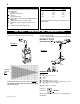
ELBOW VENT LENGTH VALUES DEFINITIONS for the following symbols used in the venting calculations and examples are: > - greater than > - equal to or greater than < - less than < - equal to or less than HT - total of both horizontal vent lengths (HR) and offsets (HO) in feet HR - combined horizontal vent lengths in feet HO - offset factor: .03(total degrees of offset - 90°*) in feet VT - combined vertical vent lengths in feet 1° 15° 30° 45° 90°* feet 0.03 0.45 0.9 1.35 2.7 inches 0.5 6.0 11.0 16.0 32.
TOP EXIT / HORIZONTAL TERMINATION when (HT) > (VT) Simple venting configuration (only one 90° elbow) FIGURE 6 See graph to determine the required vertical rise VT for the required horizontal run HT. V1 = H1 = = H2 HR = HO = ft HT = HT + VT= VT = 6 ft 3 ft 5 ft H1 + H2 = 3 + 5 = 8 ft .03 (two 90° elbows - 90°) = .03(180° - 90°) = 2.7 HR + HO = 8 + 2.7 = 10.7 ft 10.7 + 6 =16.7 Formula 1: HT < 4.2 VT Formula 2: 10.7 < 25.2 HT + VT < 24.75 feet 16.7 < 24.75 4.2 VT = 4.2 x 6 = 25.
TOP EXIT VERTICAL TERMINATION REQUIRED VERTICAL RISE IN FEET when (HT) < (VT) See graph to determine the required vertical rise VT for the required horizontal run HT. VT HORIZONTAL VENT RUN PLUS OFFSET IN FEET HT The shaded area within the lines represents acceptable values for HT and VT .
FIGURE 12 W415-0583 / D / 07.24.
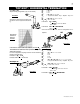
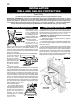
INSTALLATION WALL AND CEILING PROTECTION For optimum performance it is recommended that all horizontal runs have a minimum ¼ inch rise per foot using flexible venting. For safe and proper operation of the fireplace, follow the venting instructions exactly. HORIZONTAL TERMINATION: A clearance to combustibles of 2" must be maintained during the first 24” of venting when penetrating combustible walls. The firestop spacer (W500-0292) supplied with the unit should be used to maintain this clearance.
USING FLEXIBLE VENT COMPONENTS Use only approved aluminum flexible liner kits marked: VERTICAL AIR TERMINAL INSTALLATION “Wolf Steel Approved Venting” as identified by the stamp only on the 7” outer liner. For safe and proper operation of the fireplace, follow the venting instructions exactly.
FIREPLACE VENT CONNECTION 1. Install the 4” diameter aluminium flexible liner to the fireplace. Secure with 3 screws and flat washers. Seal the joint and screw holes using the high temperature sealant (W573-0007 not provided). 2. Install the 7” diameter aluminium flexible liner to the fireplace. Attach and seal the joints. FIGURE 20 USING RIGID VENT COMPONENTS The vent system must be supported approximately every 3 feet for both vertical and horizontal runs.
6. Remove nails from the shingles, above and to the sides of the chimney. Place the flashing over the air terminal and slide it underneath the sides and upper edge of the shingles. Ensure that the air terminal is properly centred within the flashing, giving a 3/4” margin all around. Fasten to the roof. Do NOT nail through the lower portion of the flashing. Make weathertight by sealing with caulking. Where possible, cover the sides and top edges of the flashing with roofing material. 7.
FRAMING CLEARANCE TO COMBUSTIBLES It is best to frame your fireplace after it is positioned and the vent system is installed. Use 2x4’s and frame to local building codes. Note: In order to avoid the possibility of exposed insulation or vapour barrier coming in contact with the fireplace body, it is recommended that the walls of the fireplace enclosure be “finished” (ie: drywall/sheetrock), as you would finish any other outside wall of a home.
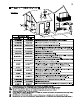
MANTLE CLEARANCES Combustible mantle clearance can vary according to the mantle depth. Use the graph to help evaluate the clearance needed. FIRESTOP SPACER 2" STUD 1" GAP FROM INSULATION SLEEVE 2" GAP FROM VENTING INSULATION SLEEVE FIGURE 32 MH AE N I TG LH ET 13 12 11 10 9 8 7 0 TOP OF UNIT 2" STAND OFF SPACER 6" MANTLE 5"4" 3" 2" 11" 9" 12" 10" 8" TOP OF FIREPLACE OPENING 1 2 3 4 5 6 7 MANTLE WIDTH ELECTRICAL CONNECTION Do NOT use the fireplace if any part has been under water.
FINISHING / SERVICING OPTIONAL FRONT REMOVAL GLASS/DOOR REPLACEMENT 1a. Rectangular Front Removal Pull on the top of the optional front away from the fireplace until the male portion of the latch disengages. Tilt forward slightly and lift from the 2 shoulder screws near the bottom. 1. Place the door frame face down careful not to scratch the paint. 1b. Heritage and Wrought Iron Front Removal Turn the head of each turn button from a horizontal position to vertical. (Fig.
BOWL, MESH & ROCK REPLACEMENT 1. Carefully slide the opening in the rear of the bowl over the burner making sure to line the holes in the bottom of the bowl with the 2 locating pins on the burner bottom. (Fig. 37) FIGURE 39 TOP SIDE OF ROCK CLUSTER CURVED DECORATIVE PANEL REMOVAL SCREW W/ SPACER FIGURE 40 FIGURE 36 2. Place the steel mesh inside the bowl making sure there is even space between the mesh and edge of bowl. (Fig. 38) TOP EDGES FIGURE 37 FIGURE 38 3.
BLOWER REPLACEMENT Your comes equipped with a heat circulating blower. The blower is pre-wired and is controlled by the remote control supplied with the unit. For control details, see operation. Pg. 20. Drywall dust will penetrate into the blower bearings, causing irreparable damage. Care must be taken to prevent drywall dust from coming into contact with the blower or its compartment. Any damage resulting from this condition is not covered by the warranty policy. 1. Turn off the power to the fireplace.
NIGHT LIGHTTM REPLACEMENT Yo u r comes equipped with our Night LightTM. The light has been pre-wired and is controlled from the remote control. If in the event the lamp or lens needs to be replaced, follow the instructions below. GASKET D E UP MBER SI Unplug the wire harness / transformer from the junction box inside the fireplace or turn off the electrical breaker for the fireplace. A FIGURE 46 LENSE FRAME Remove the four screws that secure the lens frame to the top of the firebox.
TIME OUT If the appliance is turned on and the Receiver does not receive any command for 24 hours, it automatically turns the appliance and the Remote Control off. FIREPLACE OPERATION To operate this fireplace using the remote, the pilot must be running and the gas valve turned to the “ON” position. Ensure that the receiver has power and the backup switch is in the auto position. 2. FLAME HEIGHT This function allows remote control of the flame height.
FIGURE 52 FIGURE 49 5. FAN SPEED SETTING This function controls the speed of the hot air circulating fan. To change the fan speed, use the UP and Down button until the cursor (small triangle) is left of the fan icon. Set to one of 4 levels included or turned off (level 4 means full speed) FIGURE 50 6. TIMER SETTING The Remote Control has a sleep function. With this function it is possible to set a sleep time. After this time has elapsed the appliance is automatically switched off.
ADDRESS SETTING PROCEDURE Use the UP and DOWN key on the transmitter until the cursor (small triangle) is left of the clock icon. From time 0:00 press the LEFT key ten times. The display will show then the transmitter address. Press the LEFT key to exit this function. The transmitter address is required to be equal to the Receiver. (Fig. 55) Select, through setting of the dip switches, the address of the receiver. (Fig. 57) Switch #8 must always be in the ON position (down).
DIP SWITCH NUMBER (0 = ON / 1 = OFF) 23 FIGURE 57 W415-0583 / D / 07.24.
OPERATING INSTRUCTIONS When lit for the first time, the fireplace will emit a slight odour for a few hours. This is a normal temporary condition caused by the curing of paints and lubricants used in the manufacturing process and will not occur again. Simply open a window to sufficiently ventilate the room. After extended periods of non-operation such as following a vacation or a warm weather season, the fireplace may emit a slight odour for a few hours.
MAINTENANCE TURN OFF THE GAS AND ELECTRICAL POWER BEFORE SERVICING THE FIREPLACE. CAUTION: Label all wires prior to disconnection when servicing controls. Wiring errors can cause improper and dangerous operation. Verify proper operation after servicing. This fireplace and its venting system should be inspected before use and at least annually by a qualified service person. The fireplace area must be kept clear and free of combustible materials, gasoline or other flammable vapours and liquids.
VENTURI ADJUSTMENT Closing the air shutter Air Shutter Openings will cause a more yellow 1 /2” LP flame, but can lead to carboning. Opening the 3 NG /16” air shutter will cause a more blue flame, but can cause flame lifting from the burner ports. The flame may not appear yellow immediately; allow 15 to 30 minutes for the final flame colour to be established.
REPLACEMENTS Contact your dealer for questions concerning prices and availability of replacement parts. Normally all parts can be ordered through your Napoleon® dealer or distributor. When ordering replacement parts always give the following information: FOR WARRANTY REPLACEMENT PARTS, A PHOTOCOPY OF THE ORIGINAL INVOICE WILL BE REQUIRED TO HONOUR THE CLAIM. REPLACEMENT PARTS # PART NO.
10 4 11 9 13 3 1 12 2 16 18 19 5 17 00 0:00 AUX ON 20 28 22 21 FEATURE SELECT ON/OFF 25 34 24 26 23 35 45 46 40 41 39 43 42 W415-0583 / D / 07.24.
TROUBLE SHOOTING GUIDE BEFORE ATTEMPTING TO TROUBLESHOOT, PURGE YOUR UNIT AND INITIALLY LIGHT THE PILOT AND THE MAIN BURNER WITH THE GLASS DOOR OPEN. SYMPTOM PROBLEM Main burner flame Blockage in vent. is a blue, lazy, transparent flame. Incorrect installation. TEST SOLUTION - remove blockage. In really cold conditions, ice buildup may occur on the terminal and should be removed as required. - ensure correct location of storm collars.
SYMPTOM PROBLEM Pilot burning; no gas Themostat or switch is defecto main burner; gas tive. knob is on ‘HI’; wall Wall switch wiring is defective. switch / thermostat is on. Main burner orifice is plugged. Faulty valve. Pilot goes out while Gas piping is undersized. standing; Main burner is in ‘OFF’ position. No spark at pilot burner Pilot will not light. PILOT BURNER THERMOPILE THERMOCOUPLE Main burner goes out; pilot stays on. Main burner goes out; pilot goes out.
DATE DEALER NAME SERVICE TECHNICIAN NAME SERVICE PERFORMANCE This fireplace must be serviced annually depending on usage Fireplace Service History SPECIAL CONCERNS 31 W415-0583 / D / 07.24.
NOTES W415-0583 / D / 07.24.