INSTALLER: LEAVE THIS MANUAL WITH THE APPLIANCE CONSUMER: RETAIN THIS MANUAL FOR FUTURE REFERENCE INSTALLATION AND OPERATION INSTRUCTIONS CERTIFIED UNDER CANADIAN AND AMERICAN NATIONAL STANDARDS: CSA 2.33, ANSI Z21.88 FOR VENTED GAS FIREPLACE HEATERS. GD82NT-PA NATURAL GAS GD82PT-PA PROPANE CERTIFIED FOR CANADA AND UNITED STATES USING ANSI/CSA METHODS.
TABLE of CONTENTS PG2-5 Log Shipping Bracket Decorative Brick Panel Installation Log Placement Glowing Embers AFK / WI FACE KIT Installation INTRODUCTION Warranty Fireplace Dimensions Installation Overview General Instructions General Information Care of Glass 6-11 21-22 Glass / Door Replacement Blower Replacement Burner and Valve Replacement Spark Module Battery Replacement Night LightTM Replacement VENTING Vent lengths Venting Specifications Minimum Air Terminal Location Clearances 12-18 INSTALLA
® ® ® ® The following materials and workmanship in your new NAPOLEON® gas fireplace are warranted against defects for as long as you own the fireplace. This covers: combustion chamber, heat exchanger, stainless steel burner, phazer™ logs and embers, gold plated parts against tarnishing, porcelainized enameled components and aluminum extrusion trims.
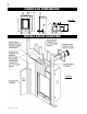
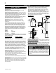
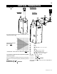
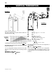
FIREPLACE DIMENSIONS 58" FIGURE 1 46" 17 / " 34 37 5/8" 4" DIA. 7" DIA. 1 21" 22 /8" 5" 2" 24" 28" 13 7/8" /" 78 8 7/8" 14" GAS INLET 28" INSTALLATION OVERVIEW FIGURE 2 W415-0665 / B / 02.11.
GENERAL INSTRUCTIONS This gas fireplace should be installed and serviced by a qualified installer to conform with local codes. Installation practices vary from region to region and it is important to know the specifics that apply to your area, for example: in Massachusetts State: • The fireplace damper must be removed or welded in the open position prior to installation of a fireplace insert or gas log. • The appliance off valve must be a “T” handle gas cock.
VENTING VENT LENGTHS For safe and proper operation of the fireplace follow the venting instruction exactly. Deviation from the minimum vertical vent length can create difficulty in burner start-up and/or carboning. Provide a means for visually checking the vent connection to the fireplace after the fireplace is installed. Vent lengths that pass through unheated spaces (attics, garages, crawl spaces) should be insulated with the insulation wrapped in a protective sleeve to minimize condensation.
ELBOW VENT LENGTH VALUES DEFINITIONS for the following symbols used in the venting calculations and examples are: > - greater than > - equal to or greater than < - less than < - equal to or less than HT - total of both horizontal vent lengths (HR) and offsets (HO) in feet HR - combined horizontal vent lengths in feet HO - offset factor: .03 (total degrees of offset - 90°*) in feet VT - combined vertical vent lengths in feet 1° 15° 30° 45° 90°* feet 0.03 0.45 0.9 1.35 2.7 inches 0.5 6.0 11.0 16.0 32.
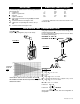
HORIZONTAL TERMINATION V1 = H1 = = H2 HR = HO = ft HT = HT + VT= when (HT) > (VT) Simple venting configuration (only one 90° elbow) FIGURE 7 See graph to determine the required vertical rise VT for the required horizontal run HT. VT = 6 ft 3 ft 5 ft H1 + H2 = 3 + 5 = 8 ft .03 (two 90° elbows - 90°) = .03(180° - 90°) = 2.7 HR + HO = 8 + 2.7 = 10.7 ft 10.7 + 6 =16.7 Formula 1: HT < 4.2 VT Formula 2: 10.7 < 25.2 HT + VT < 24.75 feet 16.7 < 24.75 4.2 VT = 4.2 x 6 = 25.
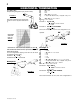
VERTICAL TERMINATION when (HT) < (VT) Example 4: FIGURE 10 FIGURE 11 90° V3 90° V1 H1 V2 H2 90° 90° See graph to determine the required vertical rise VT for the required horizontal run HT. REQUIRED VERTICAL RISE IN FEET VT HORIZONTAL VENT RUN PLUS OFFSET IN FEET HT The shaded area within the lines represents acceptable values for HT and VT .
VERTICAL TERMINATION when (HT) > (VT) FIGURE 12 90° V1 90° H1 V2 H2 90° V3 90° FIGURE 13 Example 5: Simple venting configurations See graph to determine the required vertical rise VT for the required horizontal run HT. MAXIMUM VERTICAL RISE IN FEET VT HORIZONTAL VENT RUN PLUS OFFSET IN FEET HT The shaded area within the lines represents acceptable values for HT and VT .
MINIMUM AIR TERMINAL LOCATION CLEARANCES FIGURE 14 GD-301 W415-0665 / B / 02.11.
INSTALLATION WALL AND CEILING PROTECTION HORIZONTAL VENT SECTIONS: A minimum clearance of 2” all around the vent pipe on all horizontal runs to combustibles is required. Use firestop spacer W010-1799 (supplied). VERTICAL VENT SECTIONS: A minimum of 1” all around the vent pipe on all vertical runs to combustibles is required except for clearances in fireplace enclosures. Use firestop spacer W500-0096 (not supplied).
USING FLEXIBLE VENT COMPONENTS FIGURE 19 ! ELBOW SPACERS WARNING Do not allow the inside vent pipe to bunch up on horizontal or vertical runs and elbows. Keep it pulled tight. A 1 1/4” air gap between the liner and the outer liner all around is required for safe operation. A spacer is required at the start, middle and end of each elbow to ensure this gap is maintained.
7. Aligning the seams of the terminal and air terminal connector, place the terminal over the FIGURE 22c air terminal connector making sure the liner goes into the hole in the terminal. Secure with the three screws 2” AIR INLET provided. BASE 8. Apply a heavy bead of weatherproof caulking 2” CAULKING above the flashing. NOTE: STORM COLLAR Maintain a minimum 2” space between the air inlet WEATHER SEALANT base and the storm collar.
7. Aligning the seams of the terminal and air terminal connector, place the terminal over the air terminal connector making sure the liner goes into the hole in the terminal. Secure with the three screws provided. Figure 22c 8. Apply a heavy bead of weather-proof caulking 2” above the flashing. NOTE: Maintain a minimum 2” space between the air inlet base and the storm collar. Install the storm collar around the air terminal connector and slide down to the caulking.
1" MIN 44" 62 29" /18" 22 1/2" 1" MIN FIGURE 30a-b 29" ! WARNING Do not build into this area - it must be left clear to provide adequate clearance for the vent in this 14” wide area centered along the front of the fireplace. No combustibles are allowed. FIGURE 31 3 1/2” MAXIMUM 72” MINIMUM ENCLOSURE HEIGHT 14” MINIMUM 1 1/2” MAXIMUM 22 1/2” 58 1/4” 29” W415-0665 / B / 02.11.
MINIMUM ENCLOSURE CLEARANCES Minimum clearance to combustible construction from fireplace and vent surfaces: Combustible framing: 0“ to stand-offs Non-combustible fireplace finishing: 4“ from the sides of fireplace opening 22 3/8 “ to the top of fireplace opening Combustible fireplace finishing: 0“ to rear and sides 2” all around the vent pipe 22 1/2 “ recessed depth 72“ from bottom of unit to enclosure top 72” from bottom of unit to ceiling HORIZONTAL VENT SECTIONS: A minimum clearance of 2” all around the ve
MINIMUM MANTEL AND ENCLOSURE CLEARANCES Combustible mantel clearance can vary according to the mantel depth. Use the graph to help evaluate the clearance needed.
FINISHING DOOR REMOVAL LOG SHIPPING BRACKET Before the glass door can be removed, the optional front must be removed. The glass door is secured to the top front edge of the firebox with two latches. Pull the handles of the latches forward, then lift the hooks out from the slots in the door frame to release the top of the door. Next, pivot forward until the top edge of the door clears the front of the fireplace.
LOG PLACEMENT NOTE: Decorative brick panels must be installed before the logs. See installation instructions supplied with the panel kit. PHAZERTM logs, exclusive to Napoleon® Fireplaces, provide a unique and realistic glowing effect that is different in every installation. FIGURE 39 a-f 1 1. Place the rear log #1 onto the locating studs along the back edge of the PHAZERAMIC™ burner. 5. Place log #5 so the locating hole on the bottom of the log sits on the screw and spacer. 2.
SERVICING / REPLACEMENTS GLASS/DOOR REPLACEMENT BURNER AND VALVE REPLACEMENT The glass door is secured at the top front edge of the fireplace. Pull the latch forward then lift hook out from slot in the door. Tilt door forward then lift out from retainer along the bottom edge of the fireplace. 1. Place the door frame face down careful not to scratch the paint. 2. Center the gasketed glass inside the door frame with the thick side of the gasket facing up. 3.
SPARK MODULE BATTERY REPLACEMENT 1. Remove optional front. (Instructions on Pg. 19) 2. Tilt the control panel forward and remove allowing access to the electode box which is screwed to the base of the firebox. (Fig. 53) 3. Pull back on the battery compartment door latch and remove. 4. Replace battery. 5. Reinstall battery compartment and control doors. FIGURE 53 NIGHT LIGHT™ REPLACEMENT Your comes equipped with our “Night Light™”. The light has been pre-wired and is controlled from the remote control.
HAND HELD REMOTE OPERATIONS 1. Press the ON/OFF key on the transmitter, it controls all functions of the remote. The transmitter display will show all active icons on the screen. At the same time the receiver turns on the main burner and a single “beep” from the receiver will confirm reception of the command. 2. Press the ON/OFF key on the transmitter. The transmitter LCD display will only show the room temperature and icon.
FAN SPEED LOW BATTERY / MANUAL BYPASS If the appliance is equipped with a hot air circulating fan, the speed of the fan can be controlled by the remote system. The fan speed can be adjusted through six (6) speeds. 1. Use the Mode key to guide you to the fan control icon. 2. Use the Up/Down Arrow keys to turn ON/OFF or adjust the fan speed. A single “beep” will confirm reception of the command.
OPERATING INSTRUCTIONS When lit for the first time, the fireplace will emit a slight odor for a few hours. This is a normal temporary condition caused by the curing of paints and lubricants used in the manufacturing process and will not occur again. Simply open a window to sufficiently ventilate the room. After extended periods of non-operation such as following a vacation or a warm weather season, the fireplace may emit a slight odor for a few hours.
ADJUSTMENTS PILOT BURNER ADJUSTMENT Adjust the pilot screw to provide properly sized flame. Turn in a clockwise direction to reduce the gas flow. Check Pressure Readings: (Fig. 76) Inlet pressure can be checked by turning screw (A) counter-clockwise 2 or 3 turns and then placing pressure gauge tubing over the test point. Gauge should read 7” (minimum 4.5”) water column for natural gas or 13” (11” minimum) water column for propane. Check that main burner is operating on “HI”.
REPLACEMENTS Contact your dealer for questions concerning prices and availability of replacement parts. Normally all parts can be ordered through your Napoleon® dealer or distributor. When ordering replacement parts always give the following information: 1. 2. 3. 4. 5. MODEL & SERIAL NUMBER OF FIREPLACE INSTALLATION DATE OF FIREPLACE PART NUMBER DESCRIPTION OF PART FINISH FOR WARRANTY REPLACEMENT PARTS, A PHOTOCOPY OF THE ! ORIGINAL INVOICE WILL BE REQUIRED TO HONOUR THE CLAIM.
12 35 13 11** 15 14 40 52 54 53 19 66 61 40 26 25 27 64 46 24 63 60 47 49 48 7 18 22 32 1 21 3 4 2 9 6 10 20 W415-0665 / B / 02.11.
TROUBLE SHOOTING GUIDE BEFORE ATTEMPTING TO TROUBLESHOOT, PURGE YOUR UNIT AND INITIALLY LIGHT THE PILOT AND THE MAIN BURNER WITH THE GLASS DOOR OPEN. SYMPTOM PROBLEM Main burner flame Blockage in vent. is a blue, lazy, transparent flame. Incorrect installation. TEST SOLUTION - remove blockage. In really cold conditions, ice buildup may occur on the terminal and should be removed as required. - refer to Figure 13 to ensure correct location of storm collars.
SYMPTOM PROBLEM Pilot burning; no Themostat or switch is degas to main burner; fective. gas knob is on ‘HI’; Wall switch wiring is defecwall switch / ther- tive. mostat is on. PILOT BURNER - connect a jumper wire across the wall switch terminals; if main burner lights, replace switch / thermostat. - disconnect switch wires &connect a jumper wire across terminals 1 & 3; if the main burner lights, check the wires for defects and / or replace wires. Main burner orifice is plugged.
DATE DEALER NAME SERVICE TECHNICIAN NAME SERVICE PERFORMANCE This fireplace must be serviced annually depending on usage Fireplace Service History SPECIAL CONCERNS 31 W415-0665 / B / 02.11.
NOTES W415-0665 / B / 02.11.