W415-0496 / B / 08.10.05 W415-0496 / B / 08.10.
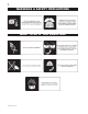
WARNINGS & SAFETY PRECAUTIONS WHAT TO DO IF YOU SMELL GAS W415-0496 / B / 08.10.
TABLE of CONTENTS 2. 4. 5. 6. 7. 8. 9. 10. 11. 15. 16. 17. 18. Finishing Glass door install and removal Cast Front Installation and removal 19. Logo Placement Log Placement 20. Operation / Maintenance 21. Adjustments Pilot Burner Adjustment Venturi Adjustment Orifice Replacement 22. Replacements Replacement Parts Accessories 24. Trouble Shooting 26.
NAPOLEON products are manufactured under the strict Standard of the world recognized ISO 9001 : 2000 Quality Assurance Certificate. NAPOLEON products are designed with superior components and materials, assembled by trained craftsmen who take great pride in their work. The burner and valve assembly are leak and test-fired at a quality test station.
GENERAL INSTRUCTIONS THIS GAS STOVE SHOULD BE INSTALLED AND SERVICED BY A QUALIFIED INSTALLER to conform with local codes. Installation practices vary from region to region and it is important to know the specifics that apply to your area, for example: in Massachusetts State: • The fireplace damper must be removed or welded in the open position prior to installation of a fireplace insert or gas log. • The appliance off valve must be a “T” handle gas cock.
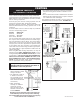
LOCATION & CLEARANCES Provide adequate accessibility clearance for servicing and operating the stove. Never obstruct the front opening of the stove. GDS20 As long as clearance to combustibles is kept within the required distances, the most desirable and beneficial location for a Napoleon stove is in the centre of a building, thereby allowing the most efficient use of the heat created. The location of windows, doors and the traffic flow in the room where the stove is to be located should be considered.
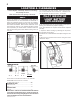
BLOWER INSTALLATION Blower (SEE LOCATION AND CLEARANCES) 1. Cut and remove the tie securing the blower switch wires to the heat shield. 2. Connect the white wire coming from below the unit to the terminal on the blower. 3. Connect the black blower wire to the black wire coming from below the unit. 4. Insert the clips on the blower housing into the cutouts in the rear shield. Push down to lock the clips into position. 5. Secure the blower using the screw and lock washer supplied.
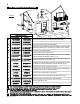
AIR TERMINAL INSTALLATIONS FIGURE 8 INSTALLATIONS CANADIAN U.S.A. A 12 INCHES 12 INCHES B 12 INCHES 9 INCHES C 12 INCHES* 12 INCHES* D 18 INCHES** Vertical clearance to ventilated soffit located above the terminal within 18 INCHES** a horizontal distance of 2 feet from the centerline of the terminal. E 12 INCHES** 12 INCHES** Clearance to unventilated soffit.
VENTING VENTING LENGTHS & AIR TERMINAL LOCATIONS Use only Wolf Steel, Simpson Dura-Vent, Selkirk Direct Temp or American Metal Amerivent venting components. For Simpson Dura-Vent, Selkirk Direct Temp and American Metal Amerivent, follow the installation procedure provided with the venting components. All outer pipe joints of these venting systems must be sealed using Red RTV High Temperature Sealant.
TYPICAL VENT INSTALLATIONS NOTE: When terminating vertically above 15', the restrictor plate must be in the fully closed position. Refer to Restricting Vertical Vents. FIGURES 3 a-c SPECIAL VENT INSTALLATIONS PERISCOPE TERMINATION Use the GD201 periscope kit to locate the air termination above grade. The periscope must be installed so that when final grading is completed, the bottom air slot is located a minimum of 12 inches above grade.
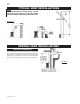
DEFINITIONS for the following symbols used in the venting calculations and examples are: > - greater than > - equal to or greater than < - less than < - equal to or less than HT - total of both horizontal vent lengths (HR) and offsets (HO) in feet HR - combined horizontal vent lengths in feet HO - offset factor: .03(total degrees of offset - 135°*) in feet VT - combined vertical vent lengths in feet ELBOW VENT LENGTH VALUES feet 0.03 0.45 0.9 1.35 2.7 1° 15° 30° 45°* 90°* inches 0.5 6.0 11.0 16.0 32.
HORIZONTAL TERMINATION when (HT) > (VT) Simple venting configuration (only one 45º and 90° elbow) See graph to determine the required vertical rise VT for the required horizontal run HT. Example 2: FIGURE 8 H1 90° 90° 45° H3 V2 H4 H2 FIGURE 7 90° V1 REQUIRED VERTICAL RISE IN INCHES (VT) = 4 ft = 1.5 ft = V1 + V2 = 4 ft + 1.5 ft = 5.5 ft = 2 ft = 1 ft = 1 ft = 1.5 ft = H1 + H2 + H3 + H4 = 2 + 1 + 1 + 1. 5 = 5.5 ft = .03(one 45º elbow + three 90º elbow -135º) =.03(315-135)=5.
VERTICAL TERMINATION when (HT) < (VT) Example 3: V2 FIGURE 9 FIGURE10 90° 45° H2 90° V1 45° H1 90° See graph to determine the required vertical rise VT for the required horizontal run HT. = 5 ft = 10 ft = V1 + V2 = 5 + 10 = 15 ft = 3 ft = 2.5 ft = H1 + H2 = 3 + 2.5 = 5.5 ft = .03(one 45º elbow + three 90º elbows - 135º) = .03(45+90+90+90-135)=5.4 HT = HR + HO = 5.5 + 5.4 = 10.9 ft HT + VT = 10.9 + 15 = 25.9 ft V1 V2 VT H1 H2 HR HO REQUIRED VERTICAL RISE IN FEET (VT) Formula 1: HT < V T 10.
VERTICAL TERMINATION when (HT) > (VT) Simple venting configurations Example 4: = 1 ft = 1.5 ft = V1 + V2 = 1 + 1.5 = 2.5 ft = 6 ft = 2 ft = H1 + H2 = 6 + 2 = 8 ft = .03(one 45º elbow + three 90º elbow - 135º) = .03(45 + 90 + 90 + 90 - 135) = 5.4 ft HT = HR + HO = 8 + 5.4 = 13.4 ft HT + VT = 13.4 + 2.5 = 15.9 ft V1 V2 VT H1 H2 HR HO FIGURE 11 Formula 1: See graph to determine the required vertical rise VT for the required horizontal run HT. REQUIRED VERTICAL RISE IN FEET (VT) HT < 3VT 3VT = 3 x 2.
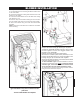
WALL AND CEILING PROTECTION FIGURE 16 VERTICAL INSTALLATION This application occurs when venting through a roof. FIGURE 17 Installation kits for various roof pitches are available from your Napoleon dealer. See Accessories to order the specific kit required. 1. Determine the air terminal location and move the stove into position. Cut and frame 9" x 10" openings in the ceiling and the roof to provide the minimum 1 inch clearance between the stove pipe and any combustible material.
HORIZONTAL VENTING INSTALLATION FOR SAFE AND PROPER OPERATION OF THE STOVE, FOLLOW THE VENTING INSTRUCTIONS EXACTLY. FOR HORIZONTAL RUNS, BOTH WOLF STEEL AND SIMPSON DURA-VENT VENTING COMPONENTS MAY HAVE A 0" RISE PER FOOT. FOR OPTIMUM PERFORMANCE IT IS RECOMMENDED THAT ALL HORIZONTAL RUNS HAVE A MINIMUM ¼ INCH RISE PER FOOT.
7. In the attic, slide the vent pipe collar down to cover up the open end of the shield and tighten. This will prevent any materials, such as insulation, from filling up the 2" air space around the pipe. STOVE VENT CONNECTION 1. Attach the adjustable pipe to the last section of rigid piping. Secure with screws and seal. 2. Install the 4" aluminium flexible liner to the stove. Secure with 3 screws and flat washers. Seal the joint and screw holes using high temperature sealant. 3.
FINISHING GLASS DOOR INSTALLATION AND REMOVAL CAST FRONT INSTALLATION AND REMOVAL Note: It is not necessary to remove the cast front, in order to remove the door. 1. Lift the top cast piece off of the unit. 2. Unlatch the door latches from the door. 3. Slide the door straight up to remove. 1. Lift the top cast piece off of the unit. 2. Detach the front cast piece from the side pieces by removing the screws from the brackets located in the upper inside corners. 3. Slide the front straight up to remove.
LOGO PLACEMENT Remove the backing from the the logo and position onto the control door as shown. LOG PLACEMENT It is not necessary to remove the cast front, however, this will make for a more simple log installation. In order to assemble the log set, the door must be removed, see Cast Front / Glass Door Removal in the FINISHING section of this manual. FIGURE 33a-d LOG LOCATING SCREWS 2. Place the hole in the underside of log #2 onto the locating screw, on the left side of the burner.
OPERATION / MAINTENANCE Purge all gas lines with the glass door removed. Assure that a continuous gas flow is at the burner before closing the door. Allow several minutes (5-15) for the flame to stabilize after ignition. OPERATING INSTRUCTIONS The on-off switch is located on the back of the unit at the top right corner on model GDS20. When lit for the first time, the fireplace will emit a slight odour for a few hours.
MAINTENANCE 2. Keep the control compartment, logs, burner, air shutTURN OFF THE GAS AND UNPLUG ter opening and the area surrounding the logs clean by ELECTRICAL POWER BEFORE SERVICING vacuuming or brushing, at least once a year. THE STOVE! 3. Check to see that all burner ports are burning. Clean CAUTION: Label all wires prior to disconnection when servicing controls. Wiring errors can cause improper and dangerous operation. Verify proper operation after servicing.
REPLACEMENTS Contact your dealer for questions concerning prices and availability of replacement parts. Normally all parts can be ordered through your Napoleon dealer or distributor. When ordering replacement parts always give the following information: FOR WARRANTY REPLACEMENT PARTS, A PHOTOCOPY OF THE ORIGINAL INVOICE WILL BE REQUIRED TO HONOUR THE CLAIM. 1. 2. 3. 4. 5. * IDENTIFIES ITEMS WHICH ARE NOT ILLUSTRATED. FOR FURTHER INFORMATION, CONTACT YOUR NAPOLEON DEALER.
* WARNING: This is a fast acting thermocouple. It is an integral safety component. Replace only with a fast acting thermocouple supplied by Wolf Steel Ltd. W415-0496 / B / 08.10.
TROUBLE SHOOTING GUIDE BEFORE ATTEMPTING TO TROUBLESHOOT, PURGE YOUR UNIT AND INITIALLY LIGHT THE PILOT AND THE MAIN BURNER WITH THE GLASS DOOR REMOVED. SYMPTOM Pilot will not light. PROBLEM No spark at pilot burner Spark gap is incorrect No gas at the pilot burner Pilot goes out when the gas knob is released. TEST SOLUTION - check if pilot can be lit by a match - check that the wire is connected to the push button ignitor. - check if the push button ignitor needs tightening.
SYMPTOM Main burner goes out; pilot goes out. Exhaust fumes smelled in room, headaches. PROBLEM TEST SOLUTION REFER TO "MAIN BURNER GOES OUT; PILOT STAYS ON" Vent re-circulating - check joint seals and installation. Thermocouple shorting or faulty. - Fireplace is spilling. loosen and tighten thermocouple clean thermocouple and valve connection. replace thermocouple. replace valve. - check all seals. Carbon is being deposited on glass, logs or combustion chamber surfaces.
Date Dealer Name Service Technician Name Service Performed This fireplace must be serviced annually depending on usage. Wolf Steel Fireplace Service History Special Concerns 26 W415-0496 / B / 08.10.
NOTES W415-0496 / B / 08.10.
NOTES W415-0496 / B / 08.10.