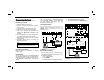
® XP-400 & RPXP4GT keypad Control Panel/Communicator Installation Instructions © NAPCO 2005 WI1370 1/05
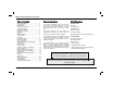
WI1370 XP-400 Installation Instructions Table of Contents General Information........................................... 2 XP-400 Features ............................................... 2 Specifications .................................................... 3 Listings and Approvals ...................................... 4 Ordering Information ......................................... 4 Optional Accessories......................................... 4 Programming the Panel.....................................
Specifications Loop Characteristics Current & Voltage Ratings Alarm Output -------------------------- Burg: 12 VDC, 2A (max.) Output Current Limiting -------------- Burg: AUX Power: 2.25 A 750 mA Residential Burglary (4 Hour Standby) Combined Standby Current: -------- 350 mA Bell Output: ---------------------------- 2 A (Using Rechargeable 12 VDC 4 AH BATTERY, minimal requirement) Transformer and Battery Required Transformer: -------------- NAPCO TRF12 OR BASLER 16.
WI1370 XP-400 Installation Instructions Listings and Approvals UL HOUSEHOLD BURGLARY WARNING SYSTEM CONTROL UNIT STANDARDS # 1023 VERIFIED TO COMPLY WITH F.C.C. PART 15 AS CLASS B : DIGITAL DEVICE European E.M.C.
Programming the Panel Refer to XP-400 Programming Instructions (WI1371) Defaulting the Panel 1. Remove power from the panel. 2. Remove all wiring from terminal 15 (PGM) and terminal 3. 3. Connect terminal 15 (PGM) to terminal 3. 4. Apply power to the XP-400 control panel. 5. After a few seconds the W ARMED, X READY and HSYSTEM TROUBLE LEDs will flash. 6. The keypad will beep 3 times indicating the panel default values have been loaded. 7. Remove wiring between terminal 15 (PGM) and terminal 3. 8.
WI1370 XP-400 Installation Instructions Installation Wiring Grounding the Panel Mounting the Panel Mount the Panel close to an unswitched AC source, a cold-water pipe ground, and a telephone line connection. Mounting the Keypad A keypad should be located near an exit/entry door. To remove the keypad from the backplate, insert a small screwdriver into the slots at the bottom of the keypad. Pull up on the screwdriver to pop off the cover.
PGM Wiring The PGM is a switched negative output that is activated depending on the programming option (s) that have been selected [08], [23] - [25]. Connect the device controlled by the PGM between +PWR and the PGM terminal (maximum load of 50 mA). Keypad Operation Keypad zone LEDs indicate zone status. W ARMED, X READY and HSYSTEM LEDs provide system status. The keypad sounder provides feedback beeps for correct and incorrect entries.
WI1370 XP-400 Installation Instructions Arming/Disarming with a Keyfob The system can be armed by pressing the key, and disarmed by pressing the L K key on the Keyfob. Zones programmed as Exit/Entry Follower Zones can be bypassed when the M or N keys on the Keyfob have been programmed for Interior [81-82]. Zones programmed as Home/Away with Delay Zones can be armed regardless of the state of the Exit/ Entry Zones when the M or N keys on the Keyfob have been programmed for Full Set [8182].
Full Setting the System with Automatic Bypassing - Home/Away with Delay Zones From the Keypad Press C B to return protection to Home/Away with Delay Zones that have been automatically bypassed. Three minutes are allowed to walk through Exit/ Entry and Exit/Entry Follower Zones. Using A Keyfob (GEM-KF) All zones in the system can be armed regardless of the state of the Exit/Entry Zone when arming with a Keyfob and using an AUX key programmed as Full Set. Press K and press and hold the M or N keys for 1.
WI1370 XP-400 Installation Instructions Zone LED Meaning OFF User Arm/Disarm Code not programmed Flashing User Arm/Code is currently being programmed Steady User Arm/Disarm Code has been programmed TABLE 4 ZONE LED DEFINITION-USER PROGRAM MODE While in User Program Mode the W Armed, X READY and HSystem Trouble LEDs will continue to flash, follow the example below to program a User 2’s code to 1923. User Mode Programming Example: 1.Press 2, Zone 2 LED will Flash 2.
Dealer Commands A6 Download of 4 to 10, with 4 being marginal and 10 being excellent. (Programming Required) Establish a connection between the PCD phone line and the Control Panel phone line. When ready, tell the installer to arm, then disarm. Then enter A6 in order to establish a connection. Phone connection to installer will go "dead" as downloader and panel connect. A7 The keypad will beep out a number, from 1-4, corresponding to the signal strength of the transmitter. See Table 5 below.
WI1370 XP-400 Installation Instructions To eliminate this fixed 20-second entry delay, also program zones as Exit/Entry Follower Zones [02]. To return protection to zones of this type, press cb from the keypad or M or N from a Keyfob. Program the Keyfob AUX 1 or AUX 2 button for Full Set [81-7]. Entry Delay allows the user time to enter and disarm. Allows exit after the panel is armed without setting off an immediate alarm and allows entry only if an Exit/Entry Zone [00] has been violated first.
[08]PGM Output Enables the PGM Output on a zone trip for each zone selected. The PGM Output will remain ON until reset. System Times [10]Exit Delay The delay time which permits exit through an Exit/Entry Zone [00] after the system is armed, allows a user to leave the premises without setting off an immediate alarm. Exit Delay may be programmed for up to 255 seconds (4¼ minutes); a value of 0 defaults to 60 seconds. may be canceled by pressing a4 before or after arming.
WI1370 XP-400 Installation Instructions [21]Keypad Features 2 (1) Audible Panic - Keypad Panic will not turn the Bell on unless this option is programmed. (2) Exit/Entry with Urgency - select to give an audible indication of Exit and Entry times. During the last 10 seconds of entry and exit time, the keypad sounds a distinct sound to indicate the premises must be left or the panel must be disarmed. (3) Display Bypassed (Armed) - Select to display bypassed zones while the panel is armed.
(3) Panic - Program to activate the PGM on a Panic alarm. (4) Test Timer - Program to activate the PGM during a Test Timer report. [25]Programmable Output Features 3 (1) AC Fail - Program to activate the PGM on the loss of AC. (15 minute delay) (2) Low Battery - Program to activate the PGM on a Low Battery condition. (3) *Trouble - Program to activate the PGM on a Trouble condition. (4) Armed - Program to activate the PGM when the panel is Armed.
WI1370 XP-400 Installation Instructions 000 033-1234 Leading Digits Report Code Subscriber ID Number FIGURE 7 DEFAULT PAGER DISPLAY (3) Single Digit - 3/1 Format. 3-digit Subscriber ID number and a 1-digit Alarm Code will be transmitted. (4) No Handshake/Pager Extend - The meaning of this option is dependent on Receiver Format programming.
[37]System Reporting, Telco 1 (1) Y AC Fail Report - Program to activate an AC Fail report (15 minute fixed report delay). (2) Low Battery Report - Program to activate a Low Battery report. (3) *Trouble Report - Program to activate a Trouble report. (4) Reserved *Includes Bell Cut, Receiver Fail-toRespond, Receiver Tamper and Receiver JAM. Point ID format will report trouble(s) by device and ID number. [38]System Restore Report, Telco 1 (1) AC Restore - Program to activate an AC Restore report.
WI1370 XP-400 Installation Instructions [61]Point ID Report Codes Telephone Number 3 Programming [50] - [59] Programming is the same as for Telco 1. Program to split/double report to Telco 3. Refer to sections [30] through [39]. Report Codes [60]Zone Report Codes Report Code for Zones 1 through 4. 4/2 format - The Zone Report Code is the 1st digit of the report code sent, the second digit is the zone number of the reporting zone. For example, if zone 2 has a reportcode of 3, the report code would be 32.
[66]Ambush Report Code Program a 2-digit report code for Ambush. To send an ambush report, program a User Code for User 4, Program report User 4 as Ambush [20-4] and Select reporting for Telco 1 [36-2] and/or Telco 3 [56-2]. Enhanced Communicator Features [68]Telephone Number 3 (1) Opening after Alarm (Cancel Code) see [67-1]. (2) Conditional Closing Telco 3 - see [671].
WI1370 XP-400 Installation Instructions [71-74] Wireless Transmitters Enter the RF ID# and the point number that is to be mapped to the zone. Programming Example Map point 1 of a window door transmitter with an RF ID# of 0012B0:0 to Zone 3. 1. Enter Dealer Mode. 2. Enter b (beeps) 73 (beeps) 3. Enter 012G200 4. Enter 1 (beeps) Note: If the RF ID# in step 3 is not entered correctly the keypad will emit a 1 second tone indicating incorrect entry. Repeat steps 2 - 4 above.
7 Full Set System Program a 7 in the AUX 1 and/or AUX 2 option to Fully Set the System when the K and the M or N buttons on the Keyfob are pressed, or when the M or N buttons are pressed when the system is armed with Exit/Entry Follower Zones or Home/Away with Delay Zones that have been bypassed.
WI1370 XP-400 Installation Instructions Site At the site perform the following three steps: 1. Arm the panel. 2. Disarm the panel. 3. Enter A6. The panel will now call the download computer running PCPreset. PCPreset will answer the call, establish a connection, and then download the account that matches the Auto Download ID Number [93] with the account of the same number in the list that PCPreset is currently running. Dealer Programming [94]Dealer Code The default Dealer Code is 4567.
System Troubles Use the System Trouble chart on the following page to determine the specific System Trouble (s). During normal panel operation the HSYSTEM return to normal operation. EXAMPLE - LOW BATTERY SYSTEM TROUBLE Press the i to enter System Trouble mode and determine the specific trouble. Press any key to view all system troubles.
WI1370 XP-400 Installation Instructions System Troubles Keypad Beeps or H SYSTEM Zone LED ON System Trouble Condition Cause/Action Flashes 1 Beep 1 Y AC Power Failure This trouble will occur if AC power is not present. Ensure that the transformer is connected to an unswitched power source. 2 Low Battery If there has been a recent power failure, the battery may be partially depleted and must be recharged by the control panel. If the trouble does not go away in 24 hours, replace the battery.
Troubleshooting 1. The bell output drops to about 3 volts in alarm. The battery/bell circuit is protected by a PC board trace which may have burned open by reversal of the battery leads. It is on the back of the PC board just adjacent to the red & black battery leads. Send in for service if this occurs. 2. How do I remove the Keypad Sounder on Alarm? The keypad sounder follows the Burg Output. If you need to remove the Keypad Sounder, then you must remove the Burg Output from that zone. 3.
WI1370 XP-400 Installation Instructions 8. How do I remove Keypad Sounder on Alarm? The keypad sounder follows the Burg Output. If you need to remove the Keypad Sounder, then you must remove the Burg Output from that zone. 9. Transmitters not responding? Open Transmitter case - Keypad should go into X-Mitter Tamper Trouble. If not: Check Receiver Red LED should be flashing once approx. once a second. Check Receiver wiring. Check Programming of Transmitter ID.
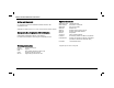
E1 XP-400 WIRING DIAGRAM + RED (REFER TO INSTALLATION INSTRUCTIONS WI1371) RECHARGEABLE BATTERY 12 VDC 4AH OR 7AH E2 BLACK RESIDENTIAL BURG (4 HOUR STANDBY) COMBINED STANDBY = 350 mA BELL = 2.0 AMP RECOMMENDED BATTERIES YUASA NP4-12 AND NP7-12 REPLACE EVERY FIVE YEARS COLD WATER GROUND CONNECTION USE ONLY COLD-WATER PIPE OR BURIED GROUND ROD. USE AT LEAST #16 AWG WIRE. NOT USED 1 2 +3 -4 +5 +6 -7 +8 -9 +10 -11 +12 -13 BELL GND 2.2K 2.
NAPCO LIMITED WARRANTY NAPCO SECURITY SYSTEMS, INC. (NAPCO) warrants its products to be free from manufacturing defects in materials and workmanship for thirty-six months following the date of manufacture. NAPCO will, within said period, at its option, repair or replace any product failing to operate correctly without charge to the original purchaser or user.