
Technical Manual
Napco iSecure Security System All technical manuals are available in PDF format at tech.napcosecurity.com 35
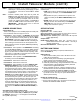
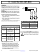
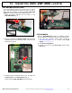
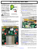
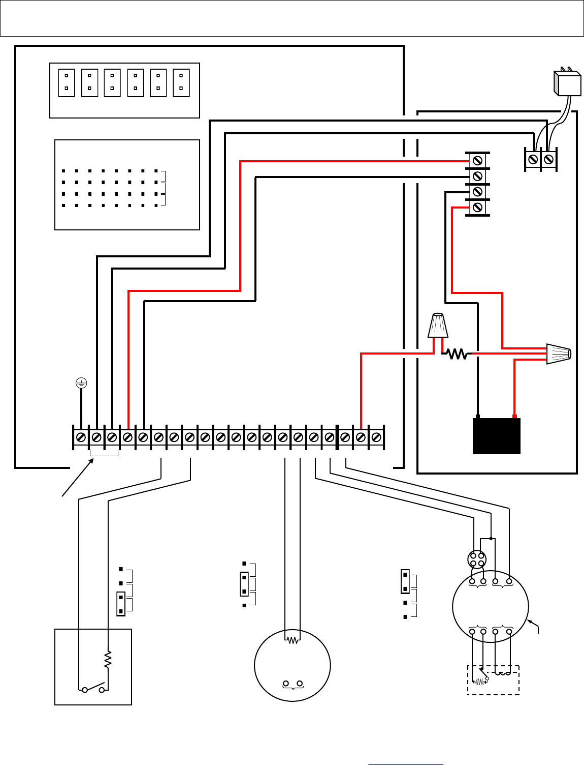
12. Install Takeover Module (cont'd)
(+)
RED
12VDC
Back Up
Battery
(–)
BLACK
EARTH
GROUND
OPTIONAL
THERMOSTAT
(–) (+)
4 WIRE
SMOKE
DETECTOR
*If the power to the CO
detector requires monitoring,
use a power monitoring relay
or other approved device.
(E)
2.2K
EOLR (part #
FT2200)
(–) (+)
FIRE
ZONE
IN
FIRE
ZONE
OUT
POWER
OUT
POWER
IN
Wiring example of a
Conventional 4-Wire
Smoke Detector
Wiring example of a
Carbon Monoxide
Detector
(–) (+)
POWER
IN*
EOLR
2.2K
Wiring example of a burglary
device; in this example, a
wired door / window contact
EOLR
2.2K
SET
JUMPER:
ZONE 1
FIRE
CO
BURG
SET
JUMPER:
ZONE 7
FIRE
CO
BURG
SET
JUMPER:
ZONE 8
FIRE
CO
BURG
P2
1 2 3 4 5 6
BAT
[‒]
BAT
[+]
DC
[‒]
DC
[+]
12-18VAC
TRANSFORMER
Control panel power or
auxiliary power supply
FIRE
CO
BURG
ZONE 8
ZONE 1
ZONE 2
ZONE 3
ZONE 4
ZONE 5
ZONE 6
ZONE 7
JP5
JP6
JP7
JP8
JP9
JP10
JP11
JP12
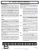
Zone Jumpers
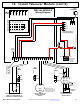
ISEC-WL-MODULE
Wiring Diagram
EARTH +12V GND‒ Z1+ Z2+ GND‒ Z3+ Z4+ GND‒ Z5+ Z6+ GND‒ Z7+ Z8+ GND‒ BATT+ PNL+
Some PCBs may
read "AC" & "AC"
or "ACL" & "ACN"
16VAC SUPV
F PWR
Battery used by
the control
panel to be
"taken over"
2.2KΩ
(Control panel enclosure)