
Technical Manual
40 All technical manuals are available in PDF format at tech.napcosecurity.com Napco iSecure Security System
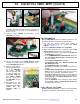
15. Install the ISEC-ZWAVE
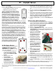
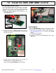
2. Re-verifying that the Go-Anywhere Smart Hub A/C and
battery power are disconnected, use Fig. 2 to locate the
two Standoff Holes located near the center of the Go-
Anywhere Smart Hub PCB (red arrows "A" and "B") and
locate the Header Socket J1 (red arrow " C").
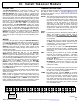
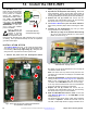
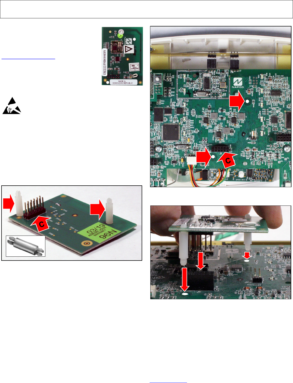
3. Carefully align the two Standoffs with their two holes, and
align the Header Plug with its Header Socket (Fig. 3).
Firmly press the ISEC-ZWAVE into the PC board.
4. Reconnect the Go-Anywhere Smart Hub A/C and battery
power. Wait 2 minutes for all devices to fully power be-
fore proceeding.
For full programming information, see OI414.
The ISEC-ZWAVE allows you to control
your Z-Wave devices through your NAP-
CO iSecure system. Note: This and all
other iSecure documents are available for
download at our Technical Library:
tech.napcosecurity.com.
The ISEC-ZWAVE requires 20mA; refer
to the "STANDBY - BATTERY CALCU-
LATION WORKSHEET" on page 72 to
verify that sufficient power is available.
Prior to opening the ISEC-ZWAVE PC
board package or touching anything inside the radio
enclosure, discharge any static electricity from your
body or clothing. Use a grounded wrist strap or
touch an unpainted, grounded metal object. Install
as follows:
ISEC-ZWAVE Installation
If the Go-Anywhere Smart Hub enclosure is not already open,
open the enclosure as directed on page 10, step 3. Remove
all A/C and battery power and install the ISEC-ZWAVE into
the iSecure Go-Anywhere Smart Hub main PCB as follows:
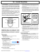
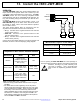
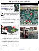
1. Insert the two plastic Standoffs (red arrows "A" and "B").
into the bottom of the ISEC-ZWAVE (Fig. 1).
ISEC-ZWAVE
Fig. 1: Two Standoffs (red arrows "A" and "B") and Header Socket J1
(red arrow "C"). Standoff shown in bottom left image.
A
B
Fig. 2: Two standoff holes ("A" & "B") and "Header Socket J1" ("C").
A
B
Fig. 3: Align and Insert the ISEC-ZWAVE.