
Technical Manual
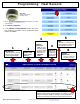

42 All technical manuals are available in PDF format at tech.napcosecurity.com Napco iSecure Security System
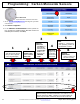
Install the ISEC-EXTANT-KIT (cont'd)
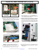
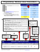
10. Route the cable through the Hub and along the
pathway shown in Fig. 6. Guide the cable to the right
and around the side "ribs" shown in Fig. 7 and down
along the bottom of the Hub PC board.
Important: To ensure maximum reception perfor-
mance, the cable must be routed along this path.
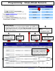
11. For strain relief, secure the cable to the PCB by
inserting the zip tie into the PCB hole shown in Fig. 8.
Before proceeding, be sure the SLE-ANTEXT anten-
na is connected to allow its immediate use when the
radio is re-powered in the next step.
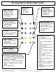
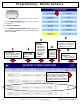
12. Close the two parts of the Hub housing, routing the
cable out the rear access door (see Fig. 9). Be sure
not to crimp the wire between the PCB and the housing.
Closing the two parts of the Hub housing will re-power
the unit, and the antenna will immediately begin trans-
mitting.
13. Re-connect AC power to the Go-Anywhere Smart
Hub by plugging in the AC transformer. Test sys-
tem operation.
Fig. 8: For strain relief, secure antenna cable to the PCB with zip tie
Fig. 6: Route the Antenna Cable to the right of the side "ribs"
as shown in this image and in Fig. 7.
Fig. 7: Route the cable around the side "ribs" (arrows) as shown.
Fig. 9: Route cable through access door. With access door in-
stalled, route cable through the opening in the bottom of the
door.
Exit here
Exit here
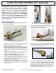
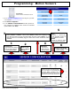
Fig. 5: Verizon and AT&T Antenna Socket Locations
For Verizon PCBs:
Use socket J502
LTE VERIZON
For AT&T PCBs:
Use socket "MAIN RF"