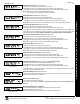
PROGRAMMING INSTRUCTIONS R Publicly traded on NASDAQ Symbol: NSSC HARDWIRE WIRELESS GEM-P3200 CONTROL PANEL/COMMUNICATOR Programming the GEM-P3200 Control Panel with the "Classic" GEM-RP1CAe2 Keypad and the "K Series" GEM-K1CA Keypad GEMINI GEMINI SYSTEM READY 01/01/06 12:00 AM SYSTEM READY 01/01/06 12:00 AM ED ARM T ST A US A 1 2 3 D NEXT/YES E PRIOR/NO F B 4 5 6 C 7 8 9 0 G AREA C O M P UT E R I ZE D S E C U R I T Y SY S T E M "Classic" GEM-RP1CAe2 ARM ED T ST A US U
THIS MANUAL INCLUDES FEATURES WHICH ARE ONLY AVAILABLE IN CONTROL PANEL FIRMWARE VERSION 50 OR LATER. IMPORTANT NOTE This manual supports the keypad programming of the GEM-P3200 control panel with the NAPCO "classic" GEMRP1CAe2 keypad as well as the GEM-K1CA "K Series" keypad. The new "K Series" GEM-K1CA model offers the new STAY and AWAY buttons with simplified functionality, along with the new MENU and ENTER buttons.
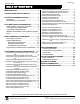
Page 3 WI818G 10/05 TABLE OF CONTENTS IMPORTANT NOTE ...................................................... 2 CHANGES FROM PREVIOUS EDITION ..................... 2 SYSTEM PROGRAMMING OPTIONS......................... 4 Introduction ............................................................... 4 Downloading from a Computer ................................. 4 EASY MENU DRIVEN PROGRAM MODE .................. 5 Dealer Program - Preliminary Information ................ 5 Accessing Dealer Program Mode.........
Page 4 WI818G 10/05 SYSTEM PROGRAMMING OPTIONS INTRODUCTION The GEM-P3200 control panel may be programmed by various means, each of which will be covered in detail in the sections that follow. Keypad displays shown are for a GEM-K1CA (v.8), the recommended keypad for programming. Downloading From a Computer. This is the preferred method of programming. The panel may be downloaded from (or uploaded to) an IBM PC-compatible computer, either locally or remotely.
Page 5 WI818G 10/05 EASY MENU DRIVEN PROGRAM MODE DEALER PROGRAM - PRELIMINARY INFORMATION Only Keypad #1 may be used for both dealer and user programming, however this keypad may be located in any area. The Master Security Code is printed on the panel’s microprocessor can. Use this code to enter the Dealer Program Mode to program a custom Dealer Security Code. Record the number, then remove the code label to prevent unauthorized access to the panel.
Page 6 WI818G 10/05 GEM-RP1CAe2/GEM-K1CA Keypad Easy Program Menu To create a custom program using the GEM-RP1CAe2/GEM-K1CA keypad, simply answer the following questions and re- cord your information on the Easy Menu Programming Worksheet. In each of the following steps, press R to set cursor, the NEXT/YES button to go forwards, the PRIOR/NO button to go backwards, U to save and C twice to exit at any time.
Page 7 WI818G 10/05 Chime 2 Zones Enter Zone # °° (Direct Entry) Chime 2 Zones in Area 1 (New Program Only) • Enter the zone numbers which are to be used as Chime 2 Zones. • Valid entries are from 01 to 48. Directly enter each zone number, including leading zeros. • Press U to save and then repeat for any additional zone(s), Press the NEXT/YES button to proceed. NOTE: A chime time of 2 seconds will be automatically programmed. Chime 2 zones give a distinct pulsating tone when zone is faulted.
Page 8 WI818G 10/05 Enable SIA CP-01 Features? Enable SIA CP-01? Y/N (Press YES or NO) # Area 1 Keypads Enter # KPs 01 GEM-RP1CAE2/GEM-K1CA KEYPAD EASY PROGRAM MENU (Direct Entry) # Area 2 Keypads Enter # KPs 00 (Direct Entry) • Press the NEXT/YES button to enable. • Press the PRIOR/NO button to continue. The SIA CP-01 Features are designed to reduce the incidence of false alarms. NOTE: unless reporting, otherwise system trouble Fail to Communicate may occur.
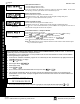
Page 9 WI818G 10/05 Central Station Receiver 1 Account Number Central Station Account # (____) (Direct Entry) • Enter an account number of up to four digits. • Press 0 through 9 for digits 0–9, and G 0 for a blank (•). • Press U to save and press the NEXT/YES button to proceed. NOTE: Central Station Receiver 2 and 3 Account Numbers must be entered in Direct Address Programming. See CS Reporting Options.
Page 10 WI818G 10/05 Enter User Codes (Press the R button to set cursor.) Enter up to 48 User Codes with User Options, Authority Level and Access Control Options (if necessary) for each code. Refer to the tables below and on the next page for available data entries for User Options, Authority Level and Access Control Options. Note: All 48 Users must be assigned to areas in “User Area Options” (Address 2455-2502) in Direct Address Programming. By default, only User 1 is enabled in Area 1 and Area 2.
Page 11 WI818G 10/05 USER AUTHORITY LEVEL KEYPAD DISPLAY FUNCTION MENU FUNCTION DISPLAY ZN FAULTS LEVEL* 1 NOTES: * Minimum Level required to access function ** Level-3 Code with appropriate user option *** Requires Dealer Code DISPLAY ZN BYPASSED 1 DISPLAY ZN DIRECTORY 1 ACTIVATE BELL TEST 1 DISPLAY PHONE #’S 1 DISPLAY SYS TRBL 1 DISPLAY FIRE ALARM 1 Disabled DISPLAY FIRE TRBL 1 Blocked View DISPLAY OP/CL 3 3** ACTIVATE CHIME 1 ACTIVATE WATCH 2 RESET SYSTEM TRBL 3 RESET SENSOR M
Page 12 WI818G 10/05 Enter Proximity Card Users (FOR ACM USE ONLY). (Press the R button to set cursor). See WI1221 for more information. Enter up to 48 Proximity Cards with User Options, Access Level and ACM Area (if necessary) for each card. Refer to the tables below and to WI1221 for more information. Enter user code 001 123456- 6User# User Code GEM-RP1CAE2/GEM-K1CA KEYPAD EASY PROGRAM MENU Press the R button to set the cursor to the User Code.
Page 13 WI818G 10/05 ZN# XMIT#+CS P Zn01- 000000:0-0 Zone # Mapped to Xmitter ID Check Sum Point # RF Transmitter Points (Press R to set cursor.) For each transmitter enter: (For wireless systems only. Also see Quick Method, which follows) • The zone number (01–48) to which the transmitter will be mapped. • The 6-digit RF ID # and 1-digit checksum number printed on the transmitter and box, • The point number (1–2); enter “9” for unsupervised (all points).
Page 14 WI818G 10/05 KeyFob Transmitters as Zone Input Devices GEM-RP1CAE2/GEM-K1CA KEYPAD EASY PROGRAM MENU (Refer to display above: press the PRIOR button to go backwards). Each of the 4 keyfob buttons can be assigned to a zone. For example, On button = point 1; Off button = point 2; A1 = point 3; A2 = point 4.
Page 15 WI818G 10/05 DIRECT ADDRESS PROGRAM MODE DIRECT ADDRESS OVERVIEW Direct Address Programming allows you to go directly to the address locations (up to 4095) and change the data entries manually in order to customize your control panel options. Whereas the Easy Menu Program Mode guides you through limited selections to get you started, Direct Address Program Mode allows you to change all options directly.
Page 16 WI818G 10/05 ZONES 1 ZONE FEATURES ADDR Z1 1 Exit/Entry Follower 8 ZONES 9 Z2 Z3 Z4 Z5 Z6 Z7 Z8 2 3 4 5 6 7 8 6 7 8 1218 ADDR 16 Z9 Z10 Z11 Z12 Z13 Z14 Z15 Z16 1 2 3 4 5 6 7 8 1318 PROGRAM THE DATA ENTRIES 1. Enter the panel's Dealer Security Code, then press R. 2. Answer NO to all questions until “ACTIVATE PROGRAM Y/N” is displayed; then press YES. NOTE: If you pass “ACTIVATE PROGRAM”, scroll backward using B. 3. Press C to enter the Address Program Mode.
Page 17 WI818G 10/05 advance to the data field. 5. Press 015. The numbers 015 will appear on the keypad display indicating the number of seconds entered. 6. Press U to save. Address 2406 is now programmed with a 15-second Abort Delay. 7. Enter another 4-digit address to continue programming or press C to exit and resume normal keypad operation. C) Hexadecimal Format Data such as Report Codes displays, accepts data by means of a Hexadecimal display.
Page 18 WI818G 10/05 PROGRAM THE DATA ENTRIES 1. Enter the panel's Dealer Security Code, then press R. 2. Answer NO to all questions until “ACTIVATE PROGRAM Y/N” is displayed; then press YES. NOTE: If you pass “ACTIVATE PROGRAM”, scroll backward using B. 3. Press C to enter the Address Program Mode. Address "0000" will display. 4. Press 0900 to access Address 0900. The existing data will display and the cursor will advance to the data field. 5.
Page 19 WI818G 10/05 SYSTEM DELAYS & TIMEOUTS (ADDRESS 0000-0002, 2402, 2406, 2414 & 3902) ADDRESS 0000 EXIT DELAY (sec.) ENTRY DELAY 1 (sec.) [Default = 030] [Default = 060] ADDRESS 0001 ENTRY DELAY 2 (sec.) ADDRESS 0002 [Default = 030] Aux. Output Access Control Timeout (sec.) ADDRESS 2402 ABORT DELAY (sec.) ADDRESS 2406 [Default = 000] [Default = 000] Telephone ADDRESS 2414 Line Test Delay (x15 sec.) Select delay/timeout (0-255 seconds).
Page 20 WI818G 10/05 SYST EM DE LA YS & TIMEOU TS ( ADDRESS 2400, 2401, 2403-2405, 4082 & 4083) Reset Output ADDRESS 2400 Timeout (min.) [Default = 000] Aux. Output Timeout (min.) ADDRESS 2401 Burg. Alarm Output Timeout (min.) [Default = 000] ADDRESS 2403 ADDRESS 2404 Pulse Alarm Output Timeout (min.) [Default = 015] [Default = 015] ADDRESS 2405 [Default = 000] Report Cancel Window (min or sec.) 1. Select delay/timeout (0-255 min.). 2.
Page 21 WI818G 10/05 C S R EC EI VE R FO RM A T O PTIO NS ( ADDR ESS 0520, 0521, 0525, 0526, 0550, 0551, 0575 & 0576) ADDRESS 0525 ADDRESS 0575 ADDRESS 0550 CS Receiver 1 Format CS Receiver 3 Format CS Receiver 2 Format Default for CS Receiver 1 Format depends on Easy Menu Question “RCVR FORMAT”. [Default = •(blank) E] for CS Receivers 1, 2 and 3 Formats.
Page 22 WI818G 10/05 CS RECEIVER T ELEPH ONE NUMBERS (ADDRESS 05 27-0546, 0552-0571, 0577-05 96) CS RECEIVER TELEPHONE NUMBERS & DOWNLOAD/CALLBACK OPTIONS ADDRESS 0527-0546 (DIGITS 1-20) CS Receiver 1 Telephone 0527 0528 0529 0530 0531 0532 0533 0534 0535 0536 0537 0538 0539 0540 0541 0542 0543 0544 0545 0546 Number (Digits 1-20) ADDRESS 0552-0571 (DIGITS 1-20) CS Receiver 2 Telephone 0552 0553 0554 0555 0556 0557 0558 0559 0560 0561 0562 0563 0564 0565 0566 0567 0568 0569 0570 0571 Number (Digits 1-20)
Page 23 WI818G 10/05 CS SUBSCRIBER ID NUMBERS (A DDRESS 0 6 50 -0 78 7) CS TELCO 1 SUBSCRIBER OPENING/CLOSING ID NUMBERS AREA 1 AREA 2 ADDRESS 0650-0653 (DIGITS 1-4) 0650 0651 0652 0653 ADDRESS 0654-0657 (DIGITS 1-4) 0654 0655 0656 0657 AREA 1 AREA 2 SYSTEM ADDRESS 0682-0685 (DIGITS 1-4) 0682 0683 0684 0685 ADDRESS 0686-0689 (DIGITS 1-4) 0686 0687 0688 0689 ADDRESS 0714-0717 (DIGITS 1-4) 0714 0715 0716 0717 CS TELCO 2 SUBSCRIBER OPENING/CLOSING ID NUMBERS (BACKUP REPORTING) AREA 1 AREA 2 ADDRE
Page 24 WI818G 10/05 C S SUBSCRIBER ID NUMBERS (A DDRESS 0 79 0-08 5 7) CS SUBSCRIBER ID NUMBERS (TELCO 3) & CS REPORTING CODES CS TELCO 3 SUBSCRIBER OPENING/CLOSING ID NUMBERS AREA 1 AREA 2 ADDRESS 0790-0793 (DIGITS 1-4) 0790 0791 0792 0793 ADDRESS 0794-0797 (DIGITS 1-4) 0794 0795 0796 0797 CS TELCO 3 SUBSCRIBER EVENT ID NUMBERS AREA 1 AREA 2 SYSTEM ADDRESS 0822-0825 (DIGITS 1-4) ADDRESS 0826-0829 (DIGITS 1-4) ADDRESS 0854-0857 (DIGITS 1-4) 0822 0823 0824 0825 0826 0827 0828 0829 0854 0855
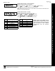
Page 25 WI818G 10/05 CS REPOR TIN G CODES (ADDRESS 0870-0904) SYSTEM REPORTING CODES ADDRESS 0870-0880 LEFT ADDR SYSTEM REPORTING CODES RIGHT ADDRESS 0890-0897 LEFT ADDR RIGHT KEYPAD REPORTING CODES ADDRESS 0900-0904 LEFT ADDR Test Timer Alarm Supervisory 0870 0871 Digital Dialer Test RESERVED 0890 0891 Ambush 0900 Panic 0901 Bus Failure 0872 RESERVED 0892 Fire 0902 Memory Failure Low Battery 0873 0874 Service Message Program Change 0893 0894 Auxiliary 0903 Tamper 0904 AC
Page 26 WI818G 10/05 CS ZONE REPORTING CODES CS ZON E REP OR TING C ODES (A DDRESS 0 91 0-09 57) ADDRESS 0910-0917 ZONES REPORT CODE (CONTROL PANEL) ZONE 1 ZONE 2 ZONE 3 ZONE 4 ZONE 5 ZONE 6 ZONE 7 ZONE 8 0910 0911 0912 0913 0914 0915 0916 0917 ADDRESS 0918-0921 ZONES REPORT CODE (GROUP 1) ZONE 9 ZONE 10 ZONE 11 ZONE 12 0918 0919 0920 0921 ADDRESS 0922-0925 ZONES REPORT CODE (GROUP 2) ZONE 13 ZONE 14 ZONE 15 ZONE 16 0922 0923 0924 0925 ADDRESS 0926-0929 ZONES REPORT CODE (GROUP 3) ZONE 17 ZONE 18 ZONE
Page 27 WI818G 10/05 CS USER REP OR TING C ODES (A DDRESS 1 0 30 -1 07 4) USERS 1 Enable Users to Report User Opening Telco 1 User Closing Telco 1 User Opening Telco 3 User Closing Telco 3 1 2 3 4 5 User Closing Telco 1 User Opening Telco 3 User Closing Telco 3 User Closing Telco 1 User Opening Telco 3 User Closing Telco 3 8 16 U9 U10 U11 U12 U13 U14 U15 U16 1 2 3 4 5 6 7 8 24 USERS 25 2 3 4 5 6 7 ADDR U25 U26 U27 U28 U29 U30 U31 U32 8 1032 1045 1058 1071 32 1 2 3 4 5 6
Page 28 WI818G 10/05 GLOBAL SYS TE M TR OUBLE RE P ORTIN G OPT IONS (ADDRES S 1082-1116) GLOBAL SYSTEM TROUBLE REPORTING OPTIONS GLOBAL SYSTEM EVENT/TROUBLE SYSTEM RESPONSE ACTIVATED BY GLOBAL EVENT/TROUBLE ADDR Burglary Alarm Output Pulsed Burg. Output Fire Output (Lug E9) Reset Relay Auxiliary Relay Report Event Telco 1 Report Restore Telco 1 Report Event Telco 3 Report Restore Telco 3 1082 1083 1084 1085 1086 1087 1088 1091 1092 TEST TIMER ALARM SUPERV. COMM.
Page 29 WI818G 10/05 AREA SYST EM T ROUBLE R EPORTING OP TI ONS (ADD RESS 11 20 -1 137 ) AREA 1 SYSTEM EVENT/TROUBLE SYSTEM RESPONSE ACTIVATED BY AREA 1 EVENT/TROUBLE ADDR Pulsed Burg. Output 1120 Burglary Output 1121 Fire Output (Lug E9) 1122 Reset Relay 1123 Auxiliary Relay 1124 Report Alarm Telco 1 Report Alarm Telco 3 1125 1127 AMBUSH KEYPAD PANIC KEYPAD FIRE KEYPAD AUX. KEYPAD TAMPER FAIL TO OPEN FAIL TO CLOSE RSRVD.
Page 30 WI818G 10/05 ZONE OPTI ONS / ZONE S 1-16 (AD DRESS 120 0 -13 8 6) ZONES 1 ZONE OPTIONS ADDR Z1 ZONE OPTIONS / ZONES 1-16 1 8 ZONES 9 Z2 Z3 Z4 Z5 Z6 Z7 2 3 4 5 6 7 16 Z8 ADDR Z9 Z10 Z11 Z12 Z13 Z14 Z15 Z16 8 1 50ms Loop Response (A) 1200 20ms Loop Response (A) Priority 1201 1202 1302 Priority with Bypass 1203 1303 Auto-Bypass 1204 1304 Selective Bypass 1205 1305 Keyswitch Arming 1206 1306 Auto-Bypass Re-entry 1207 1307 Pre-Alarm Warning 1208 1308 Never Ar
Page 31 WI818G 10/05 ZONE OPTI ONS / ZONE S 17 -32 (A DDRESS 1 40 2 -1 58 6) ZONES 17 ZONE OPTIONS 24 ZONES 25 32 ADDR Z17 Z18 Z19 Z20 Z21 Z22 Z23 Z24 ADDR Z25 Z26 Z27 Z28 Z29 Z30 Z31 Z32 1 2 3 4 5 6 7 8 1 1402 1502 Priority with Bypass 1403 1503 Auto-Bypass 1404 1504 Selective Bypass 1405 1505 Keyswitch Arming 1406 1506 Auto-Bypass Re-entry 1407 1507 Pre-Alarm Warning 1408 1508 Never Arm 1409 1509 24-Hour Zone 1410 1510 Burg.
Page 32 WI818G 10/05 ZONE OPTI ONS / ZONES 33 -48 (A DDRESS 1 6 02 -1 78 6) ZONES 33 ZONE OPTIONS ZONES 41 48 ADDR Z33 Z34 Z35 Z36 Z37 Z38 Z39 Z40 ADDR Z41 Z42 Z43 Z44 Z45 Z46 Z47 Z48 1 ZONE OPTIONS / ZONES 33-48 40 2 3 4 5 6 7 8 1 Priority 1602 1702 Priority with Bypass 1603 1703 Auto-Bypass 1604 1704 Selective Bypass 1605 1705 Keyswitch Arming 1606 1706 Auto-Bypass Re-entry 1607 1707 Pre-Alarm Warning 1608 1708 Never Arm 1609 1709 24-Hour Zone 1610 1710 Burg.
Page 33 WI818G 10/05 ZON E O PTI ONS / ZONE S 1- 4 8 (AD DRESS 12 0 0-1 7 86 ) ZONE OPTIONS: Select zone options for any zone. 1. Select the desired zone option by entering the option number (1-8) for each selected zone. 2. Enter corresponding option number in address location, in Binary (Bit) Format. NOTE: Dark shaded data value box shows option not available. Press U or D to save NOTE: See Direct Address Programming Example on page 15.
Page 34 WI818G 10/05 SYST EM OPTION S (ADDRES S 2415-2419) 2415 System Options - Disable Fire Reset Option Default System Options - Enable Day Zone Watch Option OFF 1 Disable Fire Reset (Area 1) OFF 1 Enable Day Zone Watch (Area 1) OFF 2 Disable Fire Reset (Area 2) OFF 2 Enable Day Zone Watch (Area 2) OFF 3 RESERVED OFF 3 RESERVED OFF 4 RESERVED OFF 4 RESERVED OFF 5 RESERVED OFF 5 RESERVED OFF 6 RESERVED OFF 6 RESERVED OFF 7 RESERVED OFF 7 RESERVED OFF 8 RESE
Page 35 WI818G 10/05 SYST EM OPT ION S (AD DRES S 24 20 -2 4 22, 387 4, 3 90 5, 38 8 0-38 81 ) 2420 System Options 2421 Option Default OFF 1 OFF System Options Option Default † OFF 1 Automatic Interior Bypass/Easy Exit 2 Chime on Lug E4 OFF 2 Veri-phone Zones trip Aux. Output OFF 3 Disable Code required for Func. Mode Lvl.
Page 36 WI818G 10/05 SYST EM OPT ION S (A DDRES S 3882-3901, 3903-3905 & 4084) ADDRESS 3882-3901 (RIGHT DIGITS 1-20) Telephone Dialing Prefix (Digits 1-20) 3882 3883 3884 3885 3886 3887 3888 3889 3890 3891 3892 3893 3894 3895 3896 3897 3898 3899 3900 3901 Pager Recalls ADDRESS 3903 LEFT RIGHT [Default = blank (•) blank (•)] Pager Format: Maximum Pages per Session ADDRESS 3904 LEFT RIGHT [Default = blank (•) blank (•)] SYSTEM OPTIONS LEFT DATA VALUES RESERVED 1 RESERVED 2 SYSTEM OPTIONS ADDRE
Page 37 WI818G 10/05 KEYPA D OPTION S (ADDRES S 2425-2446) Keypad 1 Type & Area Assignment ADDRESS 2425 LEFT RIGHT [Default = blank (•) 1] Keypad 5 Type & Area Assignment ADDRESS 2429 LEFT RIGHT blank (•) [Default = blank (•) blank (•)] Keypad 2 Type & Area Assignment ADDRESS 2426 LEFT RIGHT blank (•) Keypad 3 Type & Area Assignment [Default = blank (•) blank (•)] Keypad 6 Type & Area Assignment ADDRESS 2427 LEFT RIGHT blank (•) [Default = blank (•) blank (•)] ADDRESS 2430 LEFT RIGHT blank (•)
Page 38 WI818G 10/05 ACM ZONE OPTI ONS (ADDRESS 2740-2769) ACM ZONE OPTIONS: Enter the Zone numbers (in decimal 1-48 format) for each option in the table below. Press U or D to save. NOTE: Dark shaded data value box shows option not available. Note: The Area # for Door 1 is controlled by the existing Keypad Programming table (Address 2425 to 2431).
Page 39 WI818G 10/05 ACM D OOR ARE A OPTION S (AD DRESS 278 4-27 8 7) ACM DOOR AREA OPTIONS: 1. Select the desired option entering the option number (1-3) for each address. 2. Enter corresponding option number in address location. NOTE: Dark shaded data value box shows option not available. Press U or D to save.
Page 40 WI818G 10/05 KEYPAD HOME AREA / ACM DOOR #1 AR EA (HE X) (ADDR ESS 2425-2431) ACM ZONE OPTIONS: Enter the Zone numbers (in two-digit hexadecimal format) for each option in the table below. The left digit (nibble) determines the type of device: "●" for Keypad and "1" for ACM. The right digit (nibble) determines the home area (1 or 2) of the specified device. Press U or D to save.
Page 41 WI818G 10/05 SYST EM OPTION S (ADDRES S 2423) SYSTEM OPTION: 1. Select the System Option from the table shown and enter in the corresponding address location at right. Keypad Blanking will clear all data from the LCD display (and turn off all keypad LED's) after the system is armed and delay time has expired. The display will re-appear when an exit/entry door is faulted, causing an entry time delay display, or if a valid user code is entered at the keypad while the system is armed. 2.
Page 42 WI818G 10/05 USER AREA OPTIONS (ADDRESS 2455-2502) USER NUMBER USER AREA OPTIONS 1 2 3 4 5 6 7 8 9 10 11 12 13 14 15 16 17 18 19 20 21 22 23 24 25 26 27 28 29 30 31 32 33 34 35 36 37 38 39 40 41 42 43 44 45 46 47 48 ADDR 2455 2456 2457 2458 2459 2460 2461 2462 2463 2464 2465 2466 2467 2468 2469 2470 2471 2472 2473 2474 2475 2476 2477 2478 2479 2480 2481 2482 2483 2484 2485 2486 2487 2488 2489 2490 2491 2492 2493 2494 2495 2496 2497 2498 2499 2500 2501 2502 AREAS 1 2 A1 A2 1 2 ON ON ON ON
Page 43 WI818G 10/05 EZM GR OUP OPTIONS (ADDRE S S 2555- 2576) EZM Group 1 EZM Group 2 EZM Group 3 EZM Group 4 EZM Group 5 EZM Group 6 ZONES 9-12 ZONES 13-16 ZONES 17-20 ZONES 21-24 ZONES 25-28 ZONES 29-32 ADDRESS 2555 ADDRESS 2556 ADDRESS 2557 ADDRESS 2558 ADDRESS 2559 ADDRESS 2560 Default depends on Easy Menu questions: "# OF ZNS IN AREA1" and "# OF ZNS IN AREA2" For example, If 32 zones are used, then all 6 groups will be automatically enabled.
Page 44 WI818G 10/05 AREA ARMING OPTI ONS (ADDRE SS 2650-2 651) PRIORITY AREA ARMING ARMING AREA ADDRESS 1 2650 2 2651 A1 A2 1 2 AREA ARMING OPTIONS & REMOTE ACCESS LOGGING [Default = blank (•) blank (•) from address 2650-2651] PRIORITY AREA ARMING: 1. 2. 3. Select the desired arming area. Enter the corresponding Area number in each the address location, in Binary (Bit) Format. NOTE: See Direct Address Programming Example on page 15. Press U or D to save.
Page 45 WI818G 10/05 AREA OUT PUT C ONTR OL OP TI ON S (ADDRES S 2700-2739) DISARMING AREA 1 TURNS OFF AREA OUTPUT OUTPUT SILENCED (TURNED OFF) ADDR A1 A2 1 2 DISARMING AREA 2 TURNS OFF OUTPUT SILENCED (TURNED OFF) ADDR A1 A2 1 2 Burglary Output 2700 ON ON Burglary Output 2701 ON ON Pulsed Burg. Output 2708 ON ON Pulsed Burg.
Page 46 WI818G 10/05 RF RECEIVER S & SUPERVIS ORY TIMER OP TI ONS (ADDRESS 3 7 7 6 & 3 76 0 - 3 7 7 5 ) Number of RF Receivers ADDRESS 3776 0 0 Default Number of Receivers = 0 RF RECEIVERS & SUPERVISORY TIMER OPTIONS RF RECEIVERS: Up to 2 RF Receivers may be programmed. NOTE: This adds wireless capability to the system, increasing up to 48 the number of zones. 1. Select the number of receivers (1-2).
Page 47 WI818G 10/05 EXTERNAL RELAY CONTR OL / R ELAYS 1-24 (ADDRESS 3778-3801 & 2800-2895) ADDRESS 3778 & 2800-2803 (RELAY/entry 1) 3778 L R 2800 L R 2801 2802 L R ADDRESS 3779 & 2804-2807 (RELAY/entry 2) 2803 L R 3779 L R ADDRESS 3781 & 2812-2815 (RELAY/entry 4) 3781 L R 2812 L R 2813 2814 L R 2824 L R 2825 2826 L R 3782 L R 2836 L R 2837 2838 L R 3785 L R 2849 2850 L R 3788 L R L R 2860 L 2861 R 3791 L R 2863 L L R 3794 L ADDRESS 3796 & 2872-2875 (RELAY/entry 19) 379
Page 48 WI818G 10/05 EXTER NAL R ELAY CONTR OL To program, follow the 5 steps below: STEP 1: RELAY # OPTIONS: Each relay/entry can be assigned to any of the 24 available external relays from Relay Module RM3008. Multiple entries can drive the same External Relay. RELAY EVENT OPTIONS RELAY # AREA Timeout Event ID COND. L R L R L R L R (•) (•) Select the relay number from Table 1 (shown on next page); enter in corresponding left and right digit address locations.
Page 49 WI818G 10/05 EXTERNAL REL AY CONTROL RELAY EVENT OPTIONS AREA TIMEOUT EVENT ID COND. See See See See Table 2 below Table 3 below Table 4 on page 50 Tables 5A & 5B on page 51 RELAY # See Table 1 below TABLE 1 For a desired relay not listed: A. Choose a desired relay, ex: 60 B. Divide it by 16 Areas 1-2 TIMEOUTS: Each relay event can be assigned a timeout depending on Alarm Type option.
Page 50 WI818G 10/05 STEP 4: EVENT ID CODES: Each relay event can be assigned any of the available event IDs from the table. Select 2-digit Event ID from Table 4 (below); enter in corresponding address locations (left and right digit).
Page 51 WI818G 10/05 STEP 5: RELAY EVENT CONDITION OPTIONS: Each relay event can be assigned an alarm type; and an activation condition; also, select a timeout type for each. 5A. Select Alarm Type and Timeout Type from Table 5A (below); enter in corresponding address location (left digit). NOTE: Select Timeout from Step 3. 5B. Select Activation from from Table 5B (below); enter in corresponding address location (right digit).
Page 52 WI818G 10/05 SYST EM RES ET OPT ION S (A DDR ESS 40 9 1-40 93 ) Clear Dealer Program (Erases Dealer Program) 4091 XX This erases the dealer program. Use this feature to start a customized default program. GEM-RP1CAe2/GEM-K1CA Keypad DIRECT ADDRESS PROGRAM MODE--USER PROGRAM MODE GEM-RP2ASe2 Keypad 4091XX Access address 4091, then press the J or U button. Data entry is not allowed. NOTE: Enter Easy Menu Driven Program Mode to program system again.
Page 53 WI818G 10/05 ACCESSING USER PROGRAM MODE 1. Press EEEEEE R New Panel (Default User Code = 123) Existing Panel (Any Code with User Program Option Enabled) 2. Press Q Until “ACTIVATE PROGRAM Y/N” appears on LCD screen. 3. Press P To Enter User Program Mode 4. Press C To Exit User Program Mode when finished User Code Enter user code U01 123 GEMINI Enter user code U01 123 - - To Program User Codes GEM-K1CA Keypad (Direct Entry) Up to 48 User Codes may be programmed.
Page 54 WI818G 10/05 ZONE DESCRIPTIONS (GEM-RP1CAE2 / GEM-K1CA KEYPADS) Enter an identifying description for each zone. Characters are selected by pressing keypad buttons multiple times, "Cell Phone" style.
Page 55 WI818G 10/05 GEMINI KEYPAD CONFIGURATION MODE # SYSTEM ARMED # OF OF ZONES IN AREA 1 ENTER 01/01/97 12:00AM ENTER # # ZONES ZONES XXXX D ARME US STAT A123 B 456 NEXT/YES D E PRIOR/NO F AREA C7 8 9 0 G COMPUTERIZED SECURITY SYSTEM R This section will focus on configuring the GEM-RP1CAe2/GEM-K1CA Keypads. If there is more than one keypad in the system, only Keypad No. 1 may be used for programming.
Page 56 WI818G 10/05 New Compat # Compatibility Number 0000 A 4-digit Compatibility Number, if programmed, will restrict this keypad to work on a panel programmed with a matching number. 1. Enter a 4-digit number 2. Press U to save. Press the R button to continue or press the C button to exit. EZM Address EZM Address The keypad's internal EZM (Expansion Zone Module) may be utilized to provide four additional wired zones.
Page 57 WI818G 10/05 ALPHABETICAL INDEX ABORT DELAY ADDRESS 2406, 19 ABORT DELAY ZONE OPTION, 30, 31, 32 AC FAIL REPORT DELAY ADDRESS 2408, 19 ACCESS CONTROL (PANEL) ON AUX.
Page 58 WI818G 10/05 ALPHABETICAL INDEX (CONT'D) DIALING—ROTARY OR TOUCH-TONE, 25 DIGITAL DIALER RPT ENTER/EXIT TEST MODE ADDRESS 3905, 35 DIRECT ADDRESS OVERVIEW, 15 DIRECT ADDRESS PROGRAM MODE, 15 DISABLE AC FAIL DETECTION ADDRESS 2420, 35 DISABLE ANSWERING-MACHINE DOWNLOAD ADDRESS 2419, 34 DISABLE AREA ENTRY RELAYS ADDRESS 2422, 35 DISABLE AUTO-RESET ON DAY ZONE ADDRESS 2419, 34 DISABLE AUTO-UNBYPASS ON DISARMING ADDRESS 2417, 34 DISABLE AUXOUT CLEAR ON DISARM ADDRESS 2421, 35 DISABLE CALL WAITING ON F
Page 59 WI818G 10/05 ALPHABETICAL INDEX (CONT'D) 1400HZ HANDSHAKE/KISSOFF ADDRESS 0576, 21 FUNCTION MODE, 4 GEM-RP1CAE2/GEM-K1CA KEYPAD EASY PROGRAM MENU, 6 GENERAL PROGRAMMING STEPS, 18 GLOBAL SYSTEM EVENT/TROUBLE, 28 GLOBAL SYSTEM TROUBLE REPORTING OPTIONS (ADDRESS 1082-1116), 28 HANDSHAKE FOR LOCAL TELEMETRY ADDRESS 1027, 25 HEXADECIMAL FORMAT, 17 INCLUDE SEL./GRP. BYPASS IN COND.
Page 60 WI818G 10/05 ALPHABETICAL INDEX (CONT'D) RPT TROUBLE RESTORE TEL 1 ZONE OPTION, 30, 31, 32 RPT TROUBLE RESTORE TEL 3 ZONE OPTION, 30, 31, 32 RPT TROUBLE TEL 1 ZONE OPTION, 30, 31, 32 RPT TROUBLE TEL 3 ZONE OPTION, 30, 31, 32 SCHEMATIC, 68 SELECT BELL OUTPUT ON KEYFOB ARMING ADDRESS 2422, 35 SELECTIVE BYPASS ZONE OPTION, 30, 31, 32 SENSOR WATCH DELAY ADDRESS 4088, 19 SENSOR WATCH ZONE OPTION, 30, 31, 32 SENSOR WATCH ZONES, 7 SILENCE OUTPUT, 45 SINGLE DIGIT ONLY ADDRESS 0526, 21 SINGLE DIGIT ONLY AD
Page 61 WI818G 10/05 ADDRESS NUMBER INDEX ADDRESS 0000...................... EXIT DELAY ..........................................................................................................19 ADDRESS 0000-0002 ............ SYSTEM DELAYS & TIMEOUTS ...........................................................................19 ADDRESS 0001...................... ENTRY DELAY 1 ...................................................................................................19 ADDRESS 0002................
Page 62 WI818G 10/05 ADDRESS NUMBER INDEX (CONT'D) ADDRESS 0577-0596 ............ CS RECEIVER TELEPHONE NUMBERS ..............................................................22 ADDRESS 0600-0619 ............ DOWNLOAD/CALLBACK OPTIONS......................................................................22 ADDRESS 0625-0647 ............ DOWNLOAD/CALLBACK OPTIONS......................................................................22 ADDRESS 0645-0647 ............ DOWNLOAD SECURITY CODE .....................
Page 63 WI818G 10/05 ADDRESS NUMBER INDEX (CONT'D) ADDRESS 2408...................... AC FAIL REPORT DELAY .....................................................................................19 ADDRESS 2408...................... SYSTEM DELAYS & TIMEOUTS ...........................................................................19 ADDRESS 2414...................... SYSTEM DELAYS & TIMEOUTS ...........................................................................19 ADDRESS 2414......................
Page 64 WI818G 10/05 ADDRESS NUMBER INDEX (CONT'D) ADDRESS 2421...................... VERI-PHONE ZONES PRIORITY OVER ALARMS ...............................................35 ADDRESS 2421...................... VERI-PHONE ZONES TRIP AUX. OUTPUT ..........................................................35 ADDRESS 2421...................... VERI-PHONE ZONES TRIP FIRE OUTPUT ..........................................................35 ADDRESS 2422...................... DISABLE AREA ENTRY RELAYS ...............
Page 65 WI818G 10/05 ADDRESS NUMBER INDEX (CONT'D) ADDRESS 3874...................... ENABLE SET TIME/DATE MESSAGE ...................................................................35 ADDRESS 3874...................... SYSTEM OPTIONS ...............................................................................................35 ADDRESS 3874...................... SYSTEM OPTIONS ...............................................................................................35 ADDRESS 3874.................
Page 66 WI818G 10/05 NOTES X GEM-P3200 Programming Instructions L NAPCO Security Systems
Page 67 WI818G 10/05 NOTES L NAPCO Security Systems X GEM-P3200 Programming Instructions
Page 68 WI818G 10/05 GEM-P3200 WIRING DIAGRAM X GEM-P3200 Programming Instructions L NAPCO Security Systems