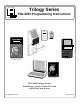
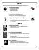
Trilogy Series PDL3000 Programming Instructions ALARM LOCK HID HID CORPORATION KEYFOB PLUG IN THEN ENTER YOUR CODE PROX CARD ALARM LOCK AR-IR1 PRINTER AL-DTM (Version 1)/AL-DTM2 DATA TRANSFER MODULE Prox Card Reader PROX CARD READER PDL3000 Trilogy Series Standalone Access Control System with ProxCard Access © ALARM LOCK 2000 WI1021 10/00 1
Features ------------------------------------------------------------------------------------------------------------------------ 4 Audit Trail ------------------------------------------------------------------------------------------------------------------ 4 User Features ------------------------------------------------------------------------------------------------------------ 4 User Access --------------------------------------------------------------------------------------------------------------- 4
Function Number 1. New Master Code -------------------------------------------------------------------------------------------------------------- 15 2. Add/Delete/Change User Codes ----------------------------------------------------------------------------------------- 15 3.-4. User Enable/Disable ---------------------------------------------------------------------------------------------------------- 16 5.
The Alarm Lock PDL3000 Series Trilogy Standalone Access Control System is a State-Of-The-Art Microprocessor Based Programmable Keypad-Entry and PROX Security Lock.
The Alarm Lock PDL3000 Series Trilogy Standalone Access Control System is a State-Of-The-Art Microprocessor Based Programmable Keypad-Entry and PROX Card Security Lock. 500 Scheduled Events * • Programmed to Unlock/Lock • Enable/Disable Users • Enable/Disable Groups • Group 1 Activated Events • 4 "Quick Schedules" - allows programming of the 4 most common time schedules in one step * AL-DTM2 transfers all 500 scheduled events. AL-DTM (Version 1) transfer first 150 scheduled events.
Ambush Function 1. Connect relay to a device able to properly monitor dry contacts for an ambush condition. 2. Program the Relay for Ambush Function Activated using Program Function 67(10). 3. Set the Ambush Code using Program Function 66. 4. When the ambush code is entered followed by a valid user code, the relay will close for 2 seconds. Ambush Code The ambush code defaults to 99. User Code An error will sound if you try to program a new user code starting with the ambush code.
Wiring Red / Black (Operation without Batteries) - Optional External 7.5 VDC Power Source must be used for operation without batteries. White / White (Remote Input) - Wire a Normally Open Contact to wires (white and white). Momentarily close to allow person to pass through door. NOTE: Remote Input is enabled from the factory. Relay: COM-Blue / NO-Yellow / NC-Green - See Function 67 for programming options for the Relay.
Lock Operation Important: Before attempting to program any codes or functions, Note the following: • While the lever or knob may be rotated at any time, the latch will not be engaged to unlock the door unless a valid code has been entered. • When a valid code is entered, the lock will unlock immediately and remain unlocked for about 3 seconds (or longer, if reprogrammed by functions 53 and 54).
Battery Installation Remove the back cover and install battery pack. The lock will beep 3 times. To load the default program press any key within 5 seconds, the lock will beep slowly while the default values are loaded and beep rapidly upon completion. Entering Program Mode 1. Enter Master Code 1 2 3 4 5 6 Program Mode Default Master Code The keypad sounder will beep every 6 seconds and the keypad LED will flash green every 6 seconds while in program mode when no keys are pressed.
User Programming Add a Basic User Code Program a User Code of 987. Use Function 2, and add the new user as User 12. Refer to Function 2 (page 15). ;2 ;12 ;987: User Number (12) Code for User 12 Add another Basic User Code Program a User Code of 246. Use Function 2, and add the new user as User 13. Refer to Function 2 (page 15).
User Programming (Continued) H H II Deleting a ProxCard/User Code Delete ProxCard Access for the ProxCard programmed for User 12. ;2 ;12 : [Beep Beep Beep Beep Beep Beep Beep Beep Beep Beep ... Beep] DO NOT Present a CARD during the 10-second period The sounder will beep rapidly for 10 seconds. DO NOT Present a CARD to the lock while the sounder is still beeping. Wait for the Sounder to stop beeping. The ProxCard and code programmed for user 12 has now been deleted.
Tri-Color Status LED Keypad Programming Infrared LED (Printer) Entering Program Mode Prox Card/Keyfob 1. Enter Master Code 1 2 3 4 5 6 PC Interface/AL-DTM2 Default Master Code 2. Press and hold ; “BeepBeep” “BeepBeep” “BeepBeep” “BeepBeep” Sounder will sound 2 short beeps 4 times to indicate the program mode is active. Program the Master Code Program Mode When no keys are pressed, the keypad sounder will beep every 6 seconds and the keypad LED will flash green every 6 seconds.
Verifying Basic Keypad User Codes Test User Code Entered in Getting Started for User 12. Enter 9 8 7 VALID CODE - The Green LED will flash momentarily and the sounder will beep a few times after a valid code is entered. INVALID CODE - The RED LED will flash several times and the sounder will beep several times after an invalid code is entered. Use Function 2 to re-program the code. Verifying Prox Card and Keyfob Access Test Prox Card programmed for User 14 in Getting Started.
For more information on PDL3000 Programming Functions see pages 15 through 28.
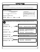
USERS ;1 1. New Master Code (User Number 1) ;[______] ;[______]: (New Master Code) • Master Code must be 6 digits-only. • Master Code is Keypad Code Access only, Prox Cards and Keyfobs cannot be programmed as the Master Code. 2. Add/Delete/Change User Codes 2-2000 ;2 (Confirm New Master Code) M ;[____] ;[______]: * (User Number) • • • • User Number must be between 2 and 2000. To delete a code/card, leave the User Code blank and wait for the rapid beeping to stop User Code must be 3-6 digits.
USERS (Continued) User Enable/Disable (By User Number) • User Number must be between 2 and 2000. NOTE: Will Enable/Disable users even if the user is associated with an enabled group. 3. Disable User ;3 2 ; [____]: (User Number) 4. Enable User 5. User Enable with Timeout ;4 ; [____]: (User Number) ;5 ;[____] ;[____]: (User Number) (Enter Timeout, XXX Hours) • User Numbers must be between 2-2000. • Hours must be between 1 - 999. • Can override a disabled user.
CLEAR FUNCTIONS 12. Clear All Schedules and Timeout ;12 ;000: Clears all programmed Schedules and all Timeout Functions. Includes Schedule Functions 72 to 93. Includes Timeout Functions 5, 25 to 34 and Function 47. NOTE: Up to 4 Timeout Functions may be pending at any one time. An error beep will sound when attempting to program more than 4 Timeout Functions. Scheduled/Timeout features must be manually reset. 13. Clear All Timeout Functions ;13 3 ;000: Clears all programmed Timeout Functions.
NOTE: GROUPS Clear All Timeout Functions by entering Function 13. Group Enable/Disable with Timeout (Enter Timeout, XXX Hours) • Hours must be between 1 - 999. Enter the functions below to Enable/Disable groups for the amount of time entered in hours. NOTE: Only 4 Timeout Functions are allowed at any one time. An error beep will sound when attempting to program more than 4 Timeout Functions. 25. Timed Disable Group 1 ;25 2 ; [___]: (XXX Hours) 26.
CLOCK SETTINGS ;38 38. Set Date ; [______]: (Date) • Use Month Day Year format - MMDDYY - Single digit months and days are entered with a preceding zero. • Enter Only the last two digits of the year. 3 For Example: March. 8, 2000; Enter: ;38 ;03 08 00: ;39 39. Set Time ; [____]: (Time) • Time must be 4 digits • Use 24 Hour Format (add 12 hours to program P.M. time) 3 For Example: To set time to 8:25 P.M.; Enter: ; 3 9 ;2025: For Example: To set time to 8:25 A.M.
CLOCK ADJUST Clock Adjust • Number of seconds to Speed Up/Slow Down clock each day must be 0-55 seconds. Always consider the current setting when using this function. (Use of this function is not cumulative.) For example, if the clock needs to be sped up 10 seconds per day and the current setting is 10, program 20 seconds using Function 43. 4 Example 1: Clock is losing 13 seconds every day, enter: ;43 ; 1 3 :. This example assumes that the clock adjust setting was at the factory default of zero.
PASSAGE MODE Passage Mode Enable/Disable - Schedule will not Override • Allows passage through the door without the need for a code using Function 48. Re-Lock using Function 49. • Programmed Schedules will not override the state of the lock using functions 48 and 49. If it is required that programmed schedules do override passage mode, Enable/Disable Passage mode using Functions 45/46. Use Function 50 to return the lock to scheduled functions. 48. Enable Passage Mode ;48: 49.
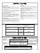
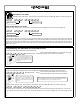
PRINTER Hold the printer perpendicular to the Lock’s infrared LED as shown in Figure 1 and Figure 2. If the printer has been idle for some time, press the paper feed button to wake up printer. Infrared LED Infrared LED 123 456 789 :0; PDL3000 to Printer - Side View PDL3000 to Printer - Front View Figure 1 55. Print Audit Trail Figure 2 ;55: Hold the printer over the lock's infrared sensor as shown in Figure 1 and Figure 2.
AL-DTM2 59. AL-DTM2 Door Number ;59 ; [__]: Door Number) • Door Number must be between 1- 96. Note: Door Number must be between 1-48 for AL-DTM (Version 1). 4 For use with Alarm Lock’s AL-DTM2 Data Transfer Module. Using the AL-DTM2 up to 96 locks can be Downloaded/Uploaded and History LOGs can be retrieved. Enter a door number for each lock.
RELAY / SYSTEM FEATURES 67. Add Relay/System Features ;67 ; [__]: (Relay Function / System Feature) 4 • Relay Functions Program 1 or more events below to activate the Relay for 2 seconds. 1. 2. 3. 4. 5. 6. Remote Input while enabled Remote Input while disabled Failed Entry Attempt Disabled User entered code/card Access Granted Scheduled (Group 1 Activated) Function 90 7. Locked by Schedule 8. Unlocked by Schedule 9. Lock Out 10. Ambush Tripped 11. Any key press/card entry 31.
ENTER KEY Enter Key • When this function is enabled the user must press the : key after any valid User Code entry; allows user codes which are subsets of other user codes. 4 Example: 1 2 3 : is a valid user code; 1 2 3 4 : is a valid user code 1 2 3 4 5 6 : (hold ; ) for Master User Code to enter Program Mode. 69. Enable : as Enter Key 70. Disable : as Enter Key 71. Reserved SCHEDULES NOTE: Clear All Schedule and Timeout Functions by entering Function 12.
QUICK SCHEDULES Quick Schedules - Enable Group • Group number must be 1-4 Enter the number of the group that is to be enabled for the time specified for the Quick Schedules below: 84. Business Quick Schedule ;84 3 ;[_]: (Group) 7AM-5PM, Monday - Friday 85. Day Quick Schedule ;85 ;[_]: (Group) 7AM-5PM, All days 86. Evening Quick Schedule ;86 ;[_]: (Group) 3PM-1AM, All days 87.
SCHEDULES GROUP 1 ACTIVATED Scheduled Relay Activation (Group 1 Activated) • Also program Relay Function 6 using Function 67 (; 6 7 ; 6 :). • For day enter: 1 for Sunday, 2 for Monday, 3 for Tuesday, 4 for Wednesday, 5 for Thursday, 6 for Friday and 7 for Saturday, 8 for Monday to Friday, 9 for Saturday and Sunday, 0 for all days of week. • Enter time of day in 24 hour format.
Scheduled Group 4 Enable (Group 1 Activated) • For day enter: 1 for Sunday, 2 for Monday, 3 for Tuesday, 4 for Wednesday, 5 for Thursday, 6 for Friday and 7 for Saturday, 8 for Monday to Friday, 9 for Saturday and Sunday, 0 for all days of week. • Enter time of day in 24 hour format. 3 Enter the Open and Close Window Functions below to set up a Window where if any Group 1 User Code is entered within the programmed window, Group 4 will be enabled. See Group 1 Member enables Group 4 Members on page 6. 92.
Note: Advanced User Programming Add a User that is a member of Group 2 & Group 3 Program a User Code of 789 that is a member of Group 2. Refer to Function 2 (page 15).
Default Values are shown in parentheses.
User Number (1-2000) User Code (3-6 digits) Group Association 1 2 3 User Name 4 Note: For a complete list of user codes, obtain a printout from either the remote printer (Program Function 56) or using the DL-WINDOWS Software.
Day(s) Function Number Up to 500 scheduled functions can be programmed (Up to only 150 using AL-DTM2).
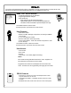
ACCESS = Entry into a restricted area. AMBUSH = An AMBUSH CODE used before a USER CODE and programmed for Relay Ambush can be used to alert security, or trip a silent-alarm on a Burglary Control Panel. AUDIT TRAIL = A log of previously date/time stamped events that have occurred. BURGLARY CONTROL PANEL = Provides local alarm and remote communication to request security for burglary/break-in. A PDL3000 relay output used for Ambush can provide a silent-alarm and call-for-help.
FUNCTION (also called Programming Functions) = are the numbers used to program lock features (enabling/disabling Users, User Groups, Passage Mode, Schedules, etc.). GROUP • USER GROUP = Defining a user to specific groups, allows user entry when the group is allowed entry. • GROUP 1 DISARMS BURGLAR CONTROL = Manager Group 1 USER CODE entry can disarm an alarm panel during a predefined schedule. Should the Manager enter outside of the scheduled time, the alarm will not disarm.
REMOTE INPUT = Entry into a restricted area, by pressing a button connected to the REMOTE INPUT WIRES (White and White) by someone on the other side of the door. SCHEDULE = A programmed operation (enable/disable, lock/unlock, etc.) on a specific weekday (Sunday through Saturday) and time. SCHEDULES, QUICK = Any one of four most common types of schedules can be programmed. TIME = Hours and Minutes in the HHMM format. TIME/DATE STAMP = A date and time that an event occurred.
ALARM LOCK LIMITED WARRANTY ALARM LOCK SYSTEMS, INC. (ALARM LOCK) warrants its products to be free from manufacturing defects in materials and workmanship for 24 months following the date of manufacture. ALARM LOCK will, within said period, at its option, repair or replace any product failing to operate correctly without charge to the original purchaser or user.
Part 15 Manual Statement The following statement should be conspicuously located in bold letters in the instruction manual: CAUTION: Changes Security Systems equipment. or modifications not expressly approved by Napco could void the user’s authority to operate the RADIO AND TELEVISION INTERFERENCE This equipment has been tested and found to comply with the limits for a Class B digital device, pursuant to Part 15 of the FCC rules.