
User's Manual

5
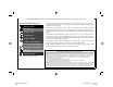
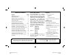
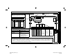
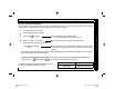
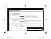
WIRING DIAGRAM AND SYSTEM CONFIGURATION
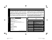
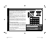
Invert Alarm Sense
A
Invert Armed Sense
B
General Information
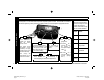
KeyFob Enroll Mode Rapid Flash
User Code Enroll Mode Rapid Flash / Pulse
Universal Mode Steady
Bus Mode Pulsing
If not pulsing in Bus Mode,
check the following:
--Keypad not programmed
--Bus wiring incorrect
Receiver LED Indications
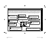
Mounting the Receiver
The 2 way receiver should be mounted in a location which is centrally located within the area of anticipated usage. It is
not recommended that the receiver be installed in an attic or mounted within 24 inches of any metallic objects.
Installation in a basement will result in reduced range. It should not be mounted in the control panel enclosure. The
receiver must be positioned with the antennas pointed up.
RES
RE4
RE3
RE2
RE1
R2T
AR
A3
A2
A1
Reserved
J1
Invert Stay PGM
J2
J3
J4
J5
Relay 2 momentary
J6
Reserved
J7
J8
J9
J10
System Configuration Jumpers
Keypad
Address
Jumpers
See
page 8
Panel
Type
Jumpers
See
page 8
A B
Enroll Mode Push Button
Receiver LED
•
•
1 2 3 4 5 6 7 8 9 10
4
1
2 3
8
5
6 7 12
9
10
11
16
13
14 15
RED +12V DC
BLACK Ground
GREEN RX
YELLOW TX
Armed Sense Input
Alarm Sense Input
PGM
N/O
COM
N/C
N/O
COM
N/C
N/O
COM
N/C
Relay 1
Keyswitch
Arm
Relay 2
Panic
Relay 3
Garage
Door
2WAY-UNIVKF_WI1024J.19_I...
page 5
Friday, February 13, 2004 08:57
Composite