
User's Manual
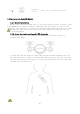
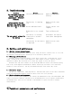
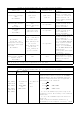
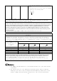
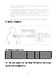

Table Of Contents
- Software specifications
- Software features
- Software functions
- 1.Introduction to “Register” and “Sign in” functions
- 2.Introduction to “Measuring ” function
- 3.Introduction to a real-time ECG waveform diagram
- 3.Introduction to “End Measurement” function
- 4.Introduction to “Data Uploading” function
- 5.Introduction to “Measurement Records” function
- 6.Introduction to “User Profile” function
- 7.Introduction of “Playback ECG” function
- 8.Introduction of online customer service function
- 9.Set Sign-in password

14
7.1 Main parameters:
Product model
SWK801
Note
Channel
Single lead
Shock proof type
CF type
Internal power supply
DC.3V
Working current
<30mA
A/DA/D conversion
16 bits
Continuous operation
time
24h
Data transmission
medium
Bluetooth
Sampling rate
=250Hz
Overall dimensions
98X35X10mm
Expected service life
5 years
Method of heart rate
calculation
Heart rate in current minute is deduced from ECG data every
10 s
Identification of
cardiac arrest
Asystole will be judged when the RR interval is greater
than a certain value
7.2 Main performance:
7.2.1 Dynamic input range
The SWCAN ECG Monitor can detect and display cardio electric signals with added DC bias
voltage of ±300mV at a change rate of 125mV/s, in increments of 10mV (peak to trough value,
gain of 10mm/mV). The error in amplitude between the time-varying output signal and the
input signal should not exceed 10% or 50uV, whichever is bigger.
7.2.2 Input impedance
Under the specified test frequency(l0Hz,5mV),the impedance of the input channel
shall be higher than 10M. This requirement shall also be met within the specified DC bias
voltage range (±300mV).
7.2.3 Common mode rejection
For the sinusoidal signals produced at the frequency of the network power supply,
common mode rejection is greater than 60dB. For signals produced at 2 times the frequency
of the network power supply, common mode rejection is greater than 45dB.
Applying a 5Hz 2mV (Peak to trough value) sinusoidal signal at input, the output signal
is equal to the input signal, with maximum amplitude error of ±10%.
7.2.4 Gain precisionProvide a 5Hz. 2mv sinusoidal signal to the input channel, output
signal equals input signal, the maximum amplitude deviation is ±10%.
7.2.5 Gain stability
After powering up the device for 1min, the fluctuation in gain is no greater than 3%
for a 4h period (in stable ambient temperature).
7.2.6 System noise
In any 10s intervals, electrical noise level converted to input does not exceed 50uV
peak-to-peak.
7.2.7 Frequency response
After applying a 3mV, 100ms square wave pulse to the device, the baseline shift should
not exceed 0.1mv, the slope after the end of the pulse should not exceed 0.3mV/s, and the
overshoot at the edge of the pulse should be less than 10%.