
UF-7 Instruction Manual Rev E

UF-7 Rev E3
1. Choose where to install, what size, and
what color LEDs are to be used. Next, choose
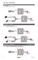
the desired UF-7 blink MODE (See Blink Mode
Section page 5).
NOTE – The blink MODE indicates
where to plug each LED into the UF-7
controller.
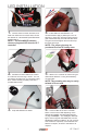
2. Drill Holes for LED Holders. Be careful
to not drill the hole too large. NOTE - You can
purchase a hand drill from your local RC hobby
store. Follow carefully all safety instructions
provided with the drill.
3. Snap LED Holders into Holes.
4. Insert LEDs into LED Holders. It is
recommended to apply a pliable glue, such as
Zap Goo or Shoe Goo, liberally making sure the
glue contacts the body, the LED and LED wires.
The glue should strengthen the wires and help
the LEDs last longer.
NOTE - The proper glue may be
purchased from an RC hobby store.
LED INSTALLATION
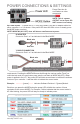
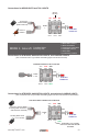
5. Attach UF-7 Controller to vehicle using it’s
double back adhesive or using the breakaway
mounting tabs.
NOTE: The mounting tabs may be easily
twisted off if not used.
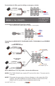
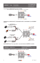
6. Connect LEDs to the UF-7 Controller
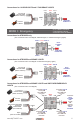
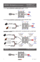
NOTE: Connect each LED depending on the
desired blink MODE. See Blink Mode Section
on page 5. Example – For headlights, tail/brake
lights, and turn signals use MODE #6, Connect
HEADLIGHT LEDs to outputs A, D or E. Connect
TAIL LIGHTS to outputs B, connect RIGHT side
blinkers to output F, and LEFT side blinkers to
output C.