
User manual
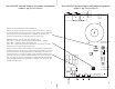

Analog Input Alignment
When using precision trimpots analog input level needs to be aligned
using an approx 1kHz sinewave fed from +4dB balanced source. The
alignment does not affect audio quality, only input sensitivity. The
alignment is performed using 10 turn trimpots. A small tweaker or
screwdriver is necessary.
You have to arbitrarily decide what will be your studio "0 VU"
analog/digital reference level. It is usually between -20 and -14dB. It
defines how much headroom you have left over the normal operating "0
VU" level. You may set it at the same level as other piece of equipment in
your studio. Some equipment is fixed at -18dB (which is low for most
rock and roll recordings) but good for more dynamic classical. Some is
fixed at -15dB which is a typical optimal level.
1.Set the oscillator in your console at 1kHz and "0 VU". Send the
oscillator to the ADC analog input."0 VU" at + 4dB corresponds to 1.225
Volts RMS measured between pin 2 and 3 of the output XLRs. If you do
not have an analog oscillator, you can use a calibrated analog out of a DA
converter and generate the sinewave inside the DAW.
2. Connect a digital PEAK meter to a digital output. If you don't have a
dedicated digital meter use the most precise meter available in you
existing digital recording equipment or DAW.
3. Adjust the analog input level to get appropriate reading of the meter
(for example -15dB).
The alignment has to be performed with accuracy of 0.1dB to be
considered accurate.
Similar alignment procedure with 0.1dB accuracy is required for valid
A/B listening comparisons btwn. different pieces of equipment. A slightly
louder source is typically perceived as "better" sounding.
Unbalanced Signal Source
Operation
Stereo192ADC can be operated with weaker consumer level unbalanced
signal sources. Follow these steps in such case.
1. Unbalanced cable used to feed the unit must have signal connected to
pin 2 of XLR, ground (shield) connected to pin 1 and while 3 must be
disconnected. Wrong wiring of this cable can cause improper operation
resulting in elevated distortion or noise.
2. Set the jumpers to "unbalanced" and disconnect both the trimpots and
potentiometer. This sets the converter to its hights sensitivity (approx -
10dB FS).
3. Setup all other connections.
4. Select desired clock source (sync), either internal or extrenal. If
external wordclock or superclock source is required for systemic reasons,
setup its mode using the DIP switch as described in "Internal jumpers".
The wordclock source can be terminated with internal 75 Ohm resistor
inside the Mytek unit (see: "Internal jumpers"). The termination is
recommended when using long wordclock cables (above 10 ft) and when
the wordclock source is capable handling such termination. Do no
terminate if the source is not capable of high current drive or cable is
short.
4. Select sampling frequency. If wordclock/superclock is used the
sampling frequency has to correspond to external clock frequency (can be
multiple, see: "Internal jumpers")
6. Synchronize the destination either to digital input sync or to wordclock
sync, depending on system configuration. The quality of recorded signal
does not depend on how the digital destination is synchronized with
Mytek AD converter.
7. Record- adjust input level by adjusting level at the source. Unless you
9
10