
User manual

SIGNAL FLOW
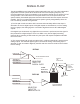
The 8X192 ADDA has two independent signal paths within the unit. They offer independent
signal paths but must operate at the same clock source and sampling frequency. It's
recommended that as much as possible the unit should be clocked from its internal CX 797
clock generator. This mode offers minimum jitter allowin for the best performance and
system stability. Associated equipment should be slaved to 8X192 clock outputs whenever
possible. There is no measurable improvement (rather typically a degradation) when the
unit is clocked by external clock generator.
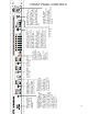
1) The first path is built around the ADC converter and essentially defines what input is
selected to be sent to digital outputs. All digital outputs are simultaneous, so if the analog
input is engaged, the analog signal is converted to digital and sent to all installed digital
outputs.
If the digital input is selected, only digital format conversion is performed, and the signal is
then passed to the digital outputs. There is no SRC or any kind of digital processing
induced. When operating in DSD mode only the inputs and outputs compatible with DSD
format are active.
"2) The second signal path is built around the DAC. It defines what signal is present at the
analog outputs. The selected digital signal is converted to analog. If the analog input is
selected, it's first converted to digital by the ADC and then sent to the DAC and converted
back to analog.
ANALOG IN
AES/EBU IN
DIOCARD1 IN
DIOCARD2 IN
ADC
TO ALL DIGITAL OUTS
PATH #1
SELECTOR
"INPUT TO
DIGITAL OUTS"
AES/EBU IN
"ANALOG IN"
DIOCARD1 IN
DIOCARD2 IN
DAC
TO 8 DISCRETE
ANALOG OUTS
PATH #2
SELECTOR
"INPUT TO
ANALOG OUTS"
STEPPED
1dB
ATTENUATOR
HEADPHONE
AMP
STEREO
XLROUTS
LEFT
RIGHT
SUMM.
BUS/ PAIR
MONITOR
SELECTOR
6