Mytek Protools-HDX DIO Card – User's Manual Mytek Protools HDX DIO Card User's Manual ver. 2.
Mytek Protools-HDX DIO Card – User's Manual This manual may be updated at any time. To download the latest version, technical support, and for setup tips please visit: http://www.mytekdigital.com Contact Mytek tech support at: hifi or at: tel. +1 (347) 384-2687 Mytek Digital 148 India St.
Mytek Protools-HDX DIO Card – User's Manual Content Content................................................................................3 Introduction.......................................................................4 Before You Begin...............................................................4 Quick Start..........................................................................5 Card Installation................................................................7 Connecting Clock Signal Line......
Mytek Protools-HDX DIO Card – User's Manual Introduction The Mytek Protools-HDX DIO Card is a physical card that plugs into the back of the Mytek 8X192 ADDA converter. With this card installed the Mytek 8X192 ADDA can be directly connected to the HDX or HD Native (Core, Process or Accel in backward compatibility mode) interface cards of Avid Pro Tools HD ® systems . The card may be installed by the user as described further in the manual.
Mytek Protools-HDX DIO Card – User's Manual Quick Start 1. DIO-HD card installation Remove the top cover from the converter, unscrew DIOCARD1 slot plate (first slot from the right while looking at the rear panel) and install the DIO-HDX card using provided screws. Double check that all the connector pins match properly with the pins of the connector on the main converter board. Check that dip switches are in the off position (for more information about dip switches function go to page 17).
Mytek Protools-HDX DIO Card – User's Manual 5. Hardware Setup Configuration Choose Setup > Hardware Setup and check sampling frequency, clock signal (should be set to Internal) and confirm Input and Output interfaces are present. Every converter in the menu should be Set to Default. 6.
Mytek Protools-HDX DIO Card – User's Manual Card Installation Only a single Protools-HDX DIO Card can be installed in one converter. A different format card can be installed in the second slot. The HD DIO card must be installed in the DIOCARD1 slot, which is first from the right at the converter’s rear panel.
Mytek Protools-HDX DIO Card – User's Manual 3. Remove top cover. 4. Locate the DIOCARD1 expansion slot on the mainboard. User's Manual ver. 2.0 / Nov 2013 www.mytekdigital.
Mytek Protools-HDX DIO Card – User's Manual 5. Unscrew cover plate of DIOCARD1 slot from the rear panel. 6. Partially insert the card from the back of the converter. User's Manual ver. 2.0 / Nov 2013 www.mytekdigital.
Mytek Protools-HDX DIO Card – User's Manual 7. Attach card ribbon cable to DIOCARD1 connector on the mainboard. 8. Gently push the card inside and secure it using four screws User's Manual ver. 2.0 / Nov 2013 www.mytekdigital.
Mytek Protools-HDX DIO Card – User's Manual 9. Screw in converter top cover. 10. Connect power and signal lines. 11. Turn the converter on. After boot up (which takes approx 20 sec) converter will switch to regular mode, and Protools-HDX DIO Card (DIOCARD1) can now be selected as signal source. User's Manual ver. 2.0 / Nov 2013 www.mytekdigital.
Mytek Protools-HDX DIO Card – User's Manual Connecting Clock Signal Line Single converter If a single converter is used in the system, choosing internal clock is the best solution. If external clock is used for synchronization, SAMPLE RATE must be set to EXT. To do this, press and hold EXT CLOCK SOURCE switch. Regardless of synchronization source, choose in Pro Tools software: Setup > Hardware Setup and select Internal on the Clock Source tab.
Mytek Protools-HDX DIO Card – User's Manual Multiple converters A Protools HD system can accept up to two converters connected to each port. Mytek DIO-HDX card allow to use four converters connected to one HD system port – for more information please read master/slave mode section in this manual. Various brands can be mixed as long as they are all capable of emulating the Avid I/O interface.
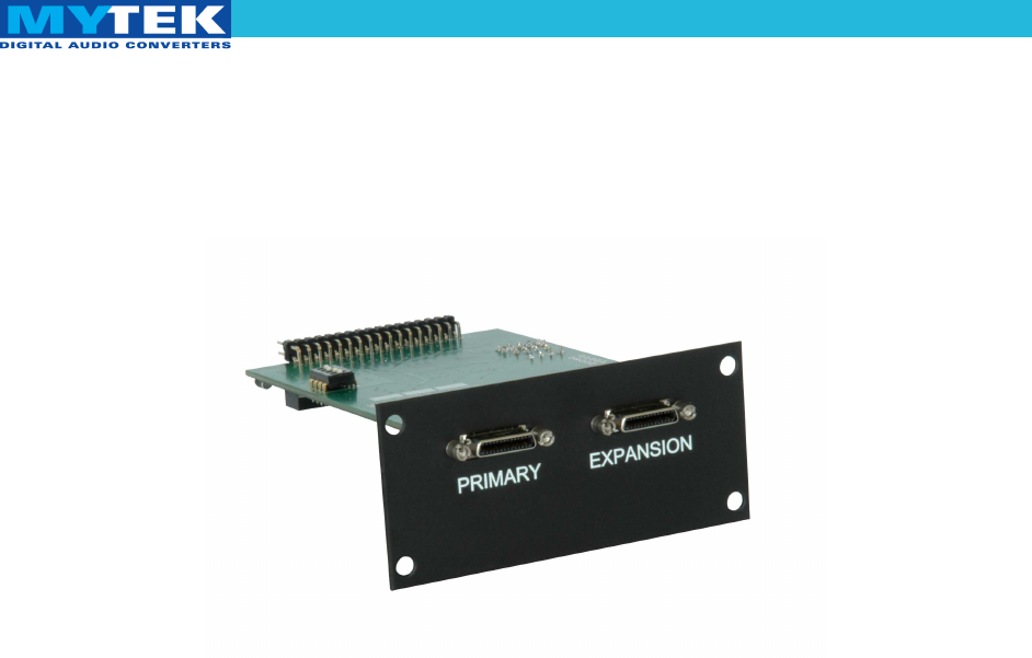
Mytek Protools-HDX DIO Card – User's Manual Input Connection The Protools DIO-HDX card features two connectors: Primary Port and Expansion Port. Functionality of these connectors is identical to Pro Tools system. Up to 4 8X192 ADDA Mytek Digital converters can be daisy chained or mixed with Avid HD I/O and other brands that emulate an HD I/O. Output connectors on the back of Ptools-HDX-DIO card.
Mytek Protools-HDX DIO Card – User's Manual Signal Routing While Protools software allows for up to 16 channels of input or output, only 8 inputs and outputs are active when single Mytek 8X192 ADDA is used. If two Mytek converter's is set to work in master/slave mode it was detected as one 16 channel converter. Input Audio signals transmitted from the 8X192 ADDA converter originate from the source selected by the switch SOURCE TO DIGITAL OUT.
Mytek Protools-HDX DIO Card – User's Manual Output To playback signal from Protools to the converter's analog outputs DIOCARD 1 SOURCE TO ANALOG OUT should be selected. If SOURCE TO DIGITAL OUT is set to DIOCARD1 as well audio is relayed from the Pro Tools system to the converter DAC (analog out) and to AES/EBU outputs as well as other digital outputs if installed. The actual signal flow in the 8X192ADDA is available in the form of schematics in the 8X192ADDA manual.
Mytek Protools-HDX DIO Card – User's Manual Master/Slave mode Dio-HDX card allow to use two 8x192ADDA's as one 16 channels converter (like HD I/O). New card is factory set to auto detect next daisy chained converter, set it to slave mode (first card is master) and reroute channels 9 to 16 to it. Slave converter isn't detected in protools system, it only expand first Mytek to 16 channels (it have fully functionality for routing, playing and recording ).
Mytek Protools-HDX DIO Card – User's Manual Launch and Configuration After the card installation in the converter, and after each hardware configuration change, interface controls must be configured in the Pro Tools application during the first launch. This is performed the following way: 1. Double check the cables connecting the converter with the Pro Tools card are properly attached. When the Pro Tools application is running do not turn the converter on or off.
Mytek Protools-HDX DIO Card – User's Manual 6. Select each converter and press Set to Default to set the application in the normal work mode. 7. In Setup > I/O Setup configure the routing according to your needs, while keeping in mind the 8X192 ADDA converter has only eight channels. If slave converter was connected it will be available 16 analog channel's. Remember that 8x192 ADDA converter has eight channels.
Mytek Protools-HDX DIO Card – User's Manual Typical Configurations Single 8x192 ADDA converter 1. Connect the 8X192 ADDA (through Primary Port) to the Pro Tools interface card in a computer. 2. Turn on the computer and converter. 3. Set the converter to work with internal clock. ✔ ✗ EXT LED shouldn’t be lit. If LED is lit, press and hold EXT CLOCK SOURCE button. 4. Launch the Pro Tools application. 5.
Mytek Protools-HDX DIO Card – User's Manual 6. If hardware configuration was changed, open Setup > Hardware Setup and press Set To Default. 7. Set Clock Source as Internal. 8. Open or create new project with a chosen frequency. ✔ ✗ LED indicating operation on the chosen frequency should lit on the front panel of the converter. If LED is not lit or other frequency is indicated, check the connection between the DIO-HDX card and the computer. 9.
Mytek Protools-HDX DIO Card – User's Manual 11. In the editing panel assign input and output channels according to the I/O Setup configuration and converter’s front panel. Editing panel – selecting input interfaces Editing panel – selecting output interfaces 12. The converter is ready to work. User's Manual ver. 2.0 / Nov 2013 www.mytekdigital.
Mytek Protools-HDX DIO Card – User's Manual Two 8x192 ADDA converters, first on internal clock (clock master), second as slave 1. Connect 8X192 ADDA converters to the Pro Tools card in a computer. ✔ Computer should be connected to the Primary Port of the first converter, while its Expansion Port should be connected to the Primary Port of the second converter. 2. Choose which converter will operate as a clock signal source (Master). 3.
Mytek Protools-HDX DIO Card – User's Manual 8. Open Setup > Hardware Setup and check: ✔ ✔ ✗ Are 8X192 ADDA Mytek Digital converters properly detected as HD I/O? Are signals input and output of each converter assigned in the Input and Output tab? If not, turn off the Pro Tools application and converters and check the connections of clock signals between converters as well as the connections between DIO-HDX cards and with computer. Setup > Hardware Setup 9.
Mytek Protools-HDX DIO Card – User's Manual 12. Use SOURCE TO DIGITAL OUT and SOURCE TO ANALOG OUT buttons to set desired signal flow in the system. ✔ ✔ Use SOURCE TO DIGITAL OUT button to select which audio signals are sent from the 8X192 ADDA converter to the Pro Tools system and converter’s digital outputs. Choose the signal transmitted to converter’s analog output by pressing SOURCE TO ANALOG OUT button. 13.
Mytek Protools-HDX DIO Card – User's Manual 14. In the editing panel assign input and output channels, according to the I/O Setup configuration and converter’s front panel. Editing panel – selecting input interfaces Editing panel – selecting output interfaces 15. Converters are ready to work User's Manual ver. 2.0 / Nov 2013 www.mytekdigital.
Mytek Protools-HDX DIO Card – User's Manual Software Update WARNING! Remember to follow basic safety rules about the handling of electronic devices while opening the converter: ✔ keep your hands dry, ✔ remember to turn off power and disconnect power and signal cables while working with the top cover removed. To perform firmware update of 8X192 ADDA converter: 1. Check if the power cord and signal and clock lines are disconnected. 2. Remove the top cover. User's Manual ver. 2.0 / Nov 2013 www.
Mytek Protools-HDX DIO Card – User's Manual 3. Locate the memory socket on the converter main board. 4. Gently remove old memory chip. To avoid damaging memory pins, remove the chip vertically. Retain old memory chip. User's Manual ver. 2.0 / Nov 2013 www.mytekdigital.
Mytek Protools-HDX DIO Card – User's Manual 5. Carefully insert new memory chip in the socket. The chip slot (pin1) should be matching the socket slot ie must be facing back of the unit. If necessary gently manually bend pins inward, to match the holes in the slot. During installation check correct chip orientation. Marks on chip and socket must be on the same side. 6. Mount the top cover back. User's Manual ver. 2.0 / Nov 2013 www.mytekdigital.
Mytek Protools-HDX DIO Card – User's Manual 7. Attach power cord and other cabling. 8. Turn on the converter. For about 2 seconds no LED's should be lit on the converter’s front panel, as new software is copied from memory to the main board chips. Then, all LED's should turn on momentarily for about 10-20sec, and subsequently the unit should begin normal operation.
Mytek Protools-HDX DIO Card – User's Manual Latency Compensantion Chart Nr Fs [kHz] Latency compensation disabled Latency compensation enabled in+out latency in+out latency Output Latency Input Latency 1. 44.1 112 30 0 30 2. 48 112 30 0 30 3. 88.2 85 41 9 32 4. 96 85 41 9 32 5. 176.4 47 7 0 7 6. 192 47 7 0 7 User's Manual ver. 2.0 / Nov 2013 www.mytekdigital.
Mytek Protools-HDX DIO Card – User's Manual Protools Mytek Compatibility Chart (Mac & Win) User's Manual ver. 2.0 / Nov 2013 www.mytekdigital.