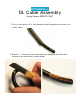
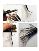
DL Cable Assembly Using Canare MR202-16AT 1. Cut a 4 inch piece of ¾ inch diameter black heatshrink and slip it on to the cable. 2. Remove ~3 inches of the outer jacket by bending the cable and cutting at the bend with a sharp blade.
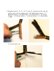
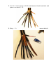
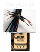
3. Separate wires 6, 12, 13, 14, 15, and 16. Cut them in half. Use the resistor color code to number wires. (Ex. Black-Brown stripe = 01, Black-Red stripe = 02, Black-Blue = 06, Brown-Red = 12, BrownOrange = 13, Brown-Yellow = 14, Brown-Green = 15, Brown-Blue = 16.) 4. Cut the nylon core.
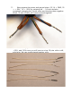
5. Cut 12 ½-inch pieces of 3/32 inch diameter black heatshrink and place it on wires 1-12. 6. Strip ~1 inch of the jacket off cables 1-12 and remove the foil.
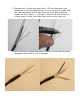
7. Separate the 3 wires and place clear 1/32 inch diameter clear heatshrink on the bare ground wire. To cut the proper length slide the clear heatshrink all the way on to the wire, then place the cutters so that it leaves ~1/8 inch of wire at the end. Hold the cutters place, lift the clear tube free from the wire, then cut. 8. Slide the piece of black heatshrink over the 3 wires and the clear heatshrink and shrink it with a heatgun.
9. Strip ~1/8 inch off the end of the other wires. 10. Proceed to crimp the pins on to cables 1-12. Be sure to use the smaller gauge crimp.
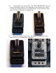
11. Now prepare the power and ground wires (13,14 = GND, 15 = +29V, 16 = -29V) by stripping off ~1/4 inch and also completely stripping the 3 inner wires and shorting them together. Wires 13 and 14 have all 6 wires twisted together. 12. Next is to prepare the male DL connector. For the GND, +29V, and -29V rows you will have to crimp 18 pins with a stiff, solid wire. We use a gold plated jewelery wire.
13. Insert them in to row H first. It is VERY IMPORTANT that you look at and take notice of the markings on the connector so that you do not accidentally pin it up-side down. Cut the wires so that only 1/8 inch of the wire is sticking up. 14. Bend the wires down with a flat head screwdriver so that they form a row. Solder them together.
15. Do steps 13-14 to rows J and K. Careful not to solder the rows together. 16. Place a small piece of black heatshrink on the GND,+, and -. GND will use a slightly larger diameter heatshrink.
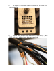
17. One end of the cable will have the wires arranged so that it will comfortably connect to the connector. The other end will be mirrored. In the case of the mirrored side, you should split the short wires in to two even groups and then bend them around all the other wires. 18. Solder wire 15 to row H. It should come on from the left side.
19. Solder the remaining ground and -29V wire. Ground should come in from the right side and wire 16 from the left. This is tricky so be patient and take your time to make sure that you do not solder the rows together and short them. 20. Insert wires 6 and 12 now. Refer to the DL pinout diagram which can be found in the PQ manual or at the end of this guide. The colored wire is +, the clear copper wire is -, and the silver wire that you put clear heatshrink over is the shield.
21. Check for shorts between the power rows with a meter. Once verified that there are indeed no shorts, hot glue the 3 rows so that they dont move around. 22. Now insert wires 7-11, starting with 11 first. It is easiest to insert the shield first, then -, then +.
23. Insert 1-5, starting with 5. 24. Now push and bend the wires so that they are flat and close to the connector. Slide the 4 inch ¾ diameter heatshrink up as far as you can and shrink it.
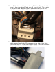
25. Prepare your DL cover. 26. Secure the half of the DL cover that has the cover tab. You'll have to maneuver the large cable through the opening to have it fit easily.
27. Snap the other half on. It is easiest if you slide the remaining half on upright from the side. You will have to bend the locking tabs on top a little bit with a flathead for the two halves to snap together. Make sure the cover tab does not get stuck under the other half. It should sit on top. Also be sure that the cable does not get pinched between the two halves. 28. Insert the top part of the strain relief by placing the tab in the hole upright, then push it down on to the cable.
29. Insert the bottom part in the same fashion. Once in, stick the large screw through both pieces and then secure it with a nut. Try not to let the heatshrink get pinched between where the bottom and top piece meet. After the strain relief is secured you can reheat the heatshrink to get rid of any scratches or if it was stretched. 30. Screw the handle on and you have completed assembly of the DL connector.
The female connector is similar in construction except that you dont cut wires 6,12,13,14,15, and 16 in half, and it is mirrored to the male DL. IMPORTANT!: ALWAYS MAKE SURE TO MATCH THE CORRECT WIRE TO THE CORRECT ROW AND COLUMN.
Reference Resistor Color Code Black = 0 Brown = 1 Red = 2 Orange = 3 Yellow = 4 Green = 5 Blue = 6 Purple = 7 Grey = 8 White = 9 Wire # (Solid-Stripe) Black-Brown = 01 Black-White = 09 Black-Red = 02 Brown-Black = 10 Black-Orange = 03 Brown-Brown = 11 Black-Yellow = 04 Brown-Red = 12 Black-Green = 05 Brown-Orange = 13 Black-Blue = 06 Brown-Yellow = 14 Black-Purple = 07 Brown-Green = 15 Black-Grey = 08 Brown-Blue = 16 DL Pinout