
Operation Manual

06
LO-LINE RC & LO-LINE RC Heater/Cooler
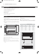
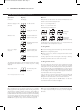
8.0 Electrical Connection
WARNING: This appliance must be earthed. The electrical installation must comply with local or national
wiring regulations.
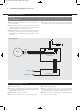
O O
LN
Motor
Power Board
Control Board
Air Sensor
Water Sensor
O O
Brown
Blue
White
Yellow
Wiring Diagram
9.0 Commissioning Procedure
l Fill and vent the system.
l Open both valves fully and vent air from the heat exchanger
by unscrewing the air bleed valve situated above the valves in
the angled top of the chassis.
l Check for leaks at pipe connections.
l Refit the outer case and secure using the 2 fixing screws.
l Switch on electrical supply.
l Check the operation of the unit in automatic and manual
modes (LO-LINE) or heating and cooling modes (LO-LINE
Heater/Cooler) by following the operating instructions.
l When installation and commissioning are complete, hand over
instruction manual to end-user.
l This unit is supplied with factory fitted test leads. Remove
these and discard.
l A fused electrical spur with a maximum 3A fuse and a switch
having 3mm separation on all poles must be provided in an
easily accessible position adjacent to the unit.
l Electrical cable entry to the unit should be made through the
underside of the unit using the cable gland provided, or
through the hole provided at the upper right hand corner of
the chassis.
l Connect live and neutral wires to the power board terminal
connections, and the earth wire to the chassis earth terminal.
23678 Lo-Line RC manual UK 27/06/2011 09:28 Page 7