
Technical data


02
KICKSPACE
®
500E
1.0 General Information
l This MYSON KICKSPACE
®
fan convector is designed for
installation in the cavity beneath kitchen cupboards on the
vacant floor space, or other similar locations.
l No rear access shall be available to the unit after installation.
l Before proceeding with the installation, the unit must be
correctly sized to meet the heat loss requirements of
the room.
l When installed under a kitchen unit consideration should be
given to storage of perishable goods in the cupboard above.
l A minimum of 25mm clear headroom is required above the
top of the KICKSPACE
®
when fitted.
l The unit should be mounted on a clean and level floor area
under the cupboard base.
l The KICKSPACE
®
fan convector is supplied with integral
controls including fan speed selector/winter switch.
l In summer mode the fan can be operated to circulate a flow
of air without any heat supply.
l Heat output performance is given in the Technical Data
section of this manual.
l Since KICKSPACE
®
units are supplied with fan speed control
it is important to size the unit to match the calculated heat
loss requirements of the room with the unit operating at the
low fan speed. The higher fan speed can then be used for
more rapid heating from cold in extreme conditions.
WARNING: THIS APPLIANCE MUST NOT BE INSTALLED IN A
BATHROOM OR OTHER SIMILAR HIGH HUMIDITY AREA.
2.0 Preparation
Before proceeding with the installation, unpack the carton
contents and check against the checklist below:
1. KICKSPACE
®
unit.
2. Instruction manual.
3. Warranty card.
4. Grill.
l A clean and level floor is required under the cupboard base.
l Decide the position of the KICKSPACE
®
, mark out and cut
the plinth to the dimensions of fig. 1. A minimum of 25mm
clearance is required above the finished floor level.
l A suitable support must be securely fitted to the floor.
The top of the support must be level with the lower edge
of the cut-out when fitted. A minimum of 25mm clear
headroom is required above the top of the KICKSPACE
®
when fitted.
3.0 Electrical Connection
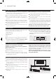
4.0 Fitting the KICKSPACE
®
l Position the KICKSPACE
®
under the cupboard in the required
location with the front edge just behind the line of the plinth.
l Replace the plinth and bring the KICKSPACE
®
forward
into the opening so the front edge projects 8mm through
the plinth (see fig. 2).
l Align the grille and secure it to the unit with two screws
supplied (use the shorter screws).
l Secure the unit/grille to the plinth with two screws supplied
(use the longer screws).
l Complete the electrical supply, switch on and test the
KICKSPACE
®
.
99
25
8mm Projection
Unit Securing Screws
Grille Securing Screws
496
WARNING: THIS APPLIANCE MUST BE EARTHED.
WARNING: THIS UNIT MUST NOT BE INSTALLED IMMEDIATELY
BELOW A SOCKET OUTLET.
l The electrical installation must comply with local or national
wiring regulations.
l This unit is supplied fitted with a 2 metre cord.
l A fused electrical spur with a switch having 3mm separation
on all poles must be provided in an easily accessible
position adjacent to the unit.
Caution: In order to avoid a hazard due to inadvertent
resetting of the thermal cut-out, this appliance must not be
supplied through an external switching device such as a timer
or room thermostat, or connected to a circuit that is regularly
switched on and off by the utility.
WARNING: DO NOT ENERGISE THE ELECTRICAL SUPPLY
UNTIL THE REMAINING STAGES OF THE INSTALLATION
HAVE BEEN COMPLETED.
Fig. 1
Fig. 2
23042 Kickspace Manual 15/02/2012 11:23 Page 3