
Operation Manual

06
HI-LINE LV Fan Convector
10.0 Technical Data
Heating Performance Data
Model Fan Speed
Temperature Difference (°C)
Heat Output (watts) Heat Output (Btu/h)
352 541 734 930 1128
645 991 1344 1702 2065
Normal
Boost
7-4
1201 1846 2504 3173 3849
2201 3381 4586 5807 7046
20° 30° 40° 50° 60° 20° 30° 40° 50° 60°
Noise Levels
Heat outputs tested in accordance with BS 4856 Part 1.
Flow rate 340 ltr/h (75 gal/h).
Flow Rate Correction Factors:
455 ltr/h (100 gal/h) multiply by 1.06.
227 ltr/h (50 gal/h) multiply by 0.96.
113 ltr/h (25 gal/h) multiply by 0.85.
Fan Speed
Sound Pressures at 2.5m (dBA)
Normal 16.6
Boost 32.5
Approximate Hydraulic Resistance through
Fan Convectors
Litres/h
455
340
227
113
mm wg
1084
798
350
134
kPa
9.4
7.7
3.5
1.4
Weight, Water Content and Motor Power
Motor
Power (W)
Water
Content (l)
Unpacked Weight
(kg)
11.0 Operating Instructions
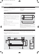
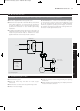
The HI-LINE LV is fitted with a fan speed and off selector switch.
Ensure that the electrical supply is switched on.
Heating will only be provided when the central heating boiler is
on, the pump is running and the system water temperature is
greater than 43°C. Ensure boiler is on, and set timer, boiler
controls and room thermostats as necessary.
Turn remote room thermostat (if fitted) to a high setting.
Set fan speed control to position I.
The unit will now run on low fan speed.
The low speed setting is recommended for normal operation
with the high speed for boost heating (position II) when required.
Low Limit Operation
A low limit thermostat fitted to the HI-LINE LV will ensure that
the fan stops after the heating system is switched off and the
water flow stops. If left in an operating position the unit will
automatically restart when the heating system is reheated.
Off Position
Set the fan speed selector switch to the off (O) position.
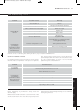
12.0 Troubleshooting
Once installed this fan convector becomes part of a complete
heating system that will generally include a boiler, pump, other
emitters such as radiators and fan convectors, and a number of
heating controls, dependent on system complexity. An apparent
problem with this unit may be the result of system controls being
incorrectly set and can be solved easily without calling out your
installer or MYSON Service. Before calling your installer or
MYSON Service, please carry out the checks listed opposite.
Note: If you call out MYSON Service to a fault detailed opposite,
or to repair a fault caused by incorrect use, a call out charge will
be made.
Noise levels tested in accordance with EN 23741.
Test Pressure 20bar (2MPa)
Maximum Working Pressure 10bar (IMPa)
Water connections 15mm
Electrical supply to transformer 230V - 50Hz
30 0.3 7.4
xxxxxx HiLine LV manual_Layout 1 27/06/2011 09:39 Page 7