
Operation Manual

05
HI-LINE LV Fan Convector
8.0 Electrical Connection
6.07.08.09.0
WARNING: The electrical installation must comply with local or national wiring regulations.
/////////////////
//
///
//
//
//
//
//
//
//
/// // // //
/
/
/////
//////
/////////
//////////
9.0 Commissioning Procedure
l Fill and vent the system.
l Open both valves fully and check for leaks at pipe
connections.
l Refit the outer case and secure using the 2 fixing screws.
l Switch on electrical supply.
l Check the operation of the unit by following the operating
instructions.
l When installation and commissioning are complete, hand over
instruction manual to end-user.
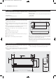
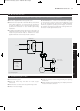
Fig. 4 Wiring diagram
Colour Code
bl = Blue
br = Brown
r = Red
y = Yellow
l This unit is supplied with a 2m long mains cord.
l A fused electrical spur with a maximum 3A fuse and a switch
having 3mm separation on all poles must be provided in
an easily accessible position. The fused spur must not be
positioned in a bathroom or other similar high humidity
installations.
l For bathroom installations this unit must be connected to an
equipotential bond using the pipe clamp provided in the
accessories pack. Attach clamp to 15mm flow or return
pipework inside the unit and attach earth conductor.
Room Thermostat - if a remote room thermostat is required
to control the fan convector, remove the link between T1 and
T2 on the terminal block and connect a suitable bimetallic
thermostat, capable of operating at low voltages, across these
two terminals. The thermostat cable entry is through the hole in
the chassis. A cable gland must be used.
5.0
Transformer
xxxxxx HiLine LV manual_Layout 1 27/06/2011 09:39 Page 6