
Owner's Manual


BT ANT
PER OUT
R
L
BYPASSAUXTAPESACDCD
R
L
SPEAKERS
LEFT
RIGHT
ONOFF
POWER
FUSE: T6.3AL /250V
USB DAC OPTICAL COAXIAL
R L
XLR
DIGITAL
INPUT
USE O NLY WITH A 250V F USE
MINIMUM SPEAKER IMPEDANCE 4
MINIMUM IMPEDANCE DES HAUT PARLEURS 4
www.myryad.co.uk
DESIGNED IN ENGLAND BY MYRYAD
SYSTEMS LTD MADE IN CHINA
POWER RATING
400W
230V
50/60Hz
S/N
3
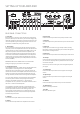
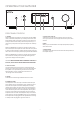
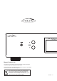
SETTING UP YOUR AMPLIFIER
REAR PANEL CONNECTIONS
1. Power inlet
Before making any connection, check that the mains voltage setting
printed on the rear panel is the same as your local mains supply. Plug
the female (socket) end of the power cord into the power inlet on the
rear of the amplifier. Plug the male (plug) end of the cord into a “live”
wall socket or a suitable heavy duty extension cable.
2. Power Switch
Press one side of this rocker switch (the side nearer the edge of the
rear panel) to switch the amplifier ON and the other side (towards the
speaker terminals) to switch it OFF. When the POWER switch is in the
OFF position all power is disconnected from the amplifier. In this
condition the amplifier cannot be powered up from the front panel
or the remote control. When the POWER switch is in the ON position
(and the power cord correctly inserted and plugged into a live wall
socket) the amplifier will power up in standby mode (see Front Panel
Controls, STANDBY).
IMPORTANT: Make sure the POWER switch is turned OFF before
making or changing any connections to the amplifier.
3. Loudspeaker outputs
The loudspeaker outputs are capable of driving all loudspeakers with
rated impedances in the range 4Ω to 16Ω The loudspeaker
terminals are high–current binding–posts, coded red or black. The
terminals on the left side of the amplifier (viewed from the front) and
marked “L” should be wired to the left-hand loudspeaker. Those on
the right, marked “R”, should be wired to the right-hand loudspeaker.
For correct stereo imaging it is important that the two loudspeakers
are wired “in phase”. To ensure correct phasing wire the black (–)
terminal on the amplifier to the black or “–” terminal on the
loudspeaker. The red (+) terminal on the amplifier should be wired to
the red or “+” terminal on the loudspeaker.
The loudspeakers should be positioned as recommended by the
loudspeaker manufacturer. The two loudspeakers should always be
placed at equal distances from the main listening position and
usually spaced a similar distance apart. It is generally best to keep
the loudspeakers away from room corners and many loudspeakers
work best away from all walls.
.
1
2
3
4
567891011121314
15
4. XLR input
Connect the audio output cables from a XLR to these sockets.
5. PER out
Connect the audio input cables from a amplifier to these sockets.
6. Bypass input
Connect the audio output cables from a preamp to these sockets.
7. AUX input
The audio output from any line level source may be connected to this
input.
8. Tape input
The Tape inputs are suited to any type of tape recorder, including
high-quality “3-head” types which allow you to monitor the signal off
the tape whilst it is being recorded.
9. SACD input
Connect the audio output cables from a SACD player to these sockets.
10. CD input
Connect the audio output cables from a CD player to these sockets. If
you do not have a CD player then any other line level source may be
connected to this input.
Note: this input is for an audio signal, not for the digital output from
your player.
15. BT ANT
Receive for bluetooth signal.
13. USB DAC
Connect the audio output cables from a pc to these usb sockets.
11. Coaxial input
Connect the audio output cables from a CD player to these digital
sockets.
12. Optical input
Connect the audio output cables from a CD player to these digital
sockets.
14. USB disk input
USB for connecting external disk.