
Operating Instruction
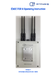


EDGE FCR 3 Operating Instruction
Page 6 of 64 Release Rev. C, 2019-09-10
© MYNXG Product GmbH, 2019. All rights reserved
List of Figures
Figure 1: EDGE FCR 3 identification label (example)..................................................................... 15
Figure 2: Desk placement of the MYNXG EDGE FCR 3 ................................................................. 17
Figure 3: DIN Rail implementation at the MYNXG EDGE FCR 3. .................................................. 17
Figure 4: MYNXG EDGE FCR 3 with antennas ................................................................................ 18
Figure 5: Side Wall 145, (UCS SW 145 F MYNXG POWER) ........................................................... 19
Figure 6:Side Wall 145, (UCS SW 145-F MYOMEGA DATA D31) ................................................. 19
Figure 7: Functional Block Diagram ................................................................................................. 22
Figure 8: EDGE FCR 3 packaging ...................................................................................................... 23
Figure 9: Mounting the standing step 1 .......................................................................................... 24
Figure 10: Mounting the standing step 2 ........................................................................................ 24
Figure 11: Removing the standing step 1 ....................................................................................... 25
Figure 12: Removing the standing step 2 ....................................................................................... 25
Figure 13: Drilling distances for the EDGE FCR 3 standings ........................................................ 26
Figure 14: DIN-rail fixture ................................................................................................................... 27
Figure 15: Releasing the DIN-rail fixture .......................................................................................... 27
Figure 16: Mounting height of MYNXG EDGE FCR 3 ..................................................................... 28
Figure 17: Wi-Fi Analyzer App ........................................................................................................... 29
Figure 18: Antennas for LTE and Sub-1GHz networks with SMA Male connector ................... 30
Figure 19: Wi-Fi “Rowing Stick” antenna with RP-SMA female connector ................................. 30
Figure 20: Power Supply Meanwell GST36E24 .............................................................................. 31
Figure 21: Standard DC output plug ................................................................................................. 32
Figure 22: Connectors for 24VDC input power .............................................................................. 32
Figure 23: Inserting cable into push-in spring socket ................................................................... 33
Figure 24: Releasing the cable from the push-in spring socket ................................................... 34
Figure 25: EDGE FCR 3 power site ................................................................................................... 35
Figure 26: DB-9 socket female pins ................................................................................................. 36
Figure 27: EDGE FCR 3.data site labeling connector ..................................................................... 37
Figure 28: HART and current loop interface ................................................................................... 38
Figure 29: Analog input interface ..................................................................................................... 39
Figure 30: I
2
C interface ...................................................................................................................... 39