
Operating Instruction

EDGE FCR 3 Operating Instruction
Rev. C, 2019-09-10 Release Page 53 of 64
© MYNXG Product GmbH, 2019. All rights reserved
6.8 Analog Input / Output Specifications
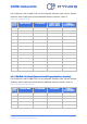
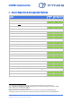
The analog inputs / outputs are exposed at the terminal block “Analog Input / Output” to host
analog sensors. The analog input signals are specified according to Table 15 below:
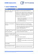
Table 15: Analog Input voltages
Parameter
Min
Typ.
Max
Unit
Conditions
Analog Input Voltage
0
12
V
-
Ground Signal GND
-
0
-
V
Ground potential
Voltage OUT
-
3.3
-
V
Supply voltage for analogue sensor
Voltage OUT
-
5
-
V
Supply voltage for analogue sensor
Voltage OUT
-
12
-
V
Supply voltage for analogue sensor
6.9 Digital I
2
C Interface Specifications
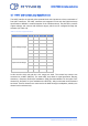
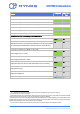
The I²C bus is exposed at the terminal block “I²C Interface” can be used to host MYNXG digital
sensors. The I²C interface is specified according to Table 16 below and does have an internal
4.7kohm pull-up resistor:
Table 16: I
2
C specifications
Parameter
Min
Typ.
Max
Unit
Conditions
I
2
C clock rate range
10
-
400
kHz
-
I
2
C bus input H-level
1.3
-
3.6
V
VDD is 3.3V
I
2
C bus input L-level
-
-
0.5
V
VDD is 3.3V
I²C CLK
-
-
3.6
V
I²C bus specification H- / L-Level
I²C DAT
-
-
3.6
V
I²C bus specification H- / L-Level
3.3V OUT
-
3.3
-
V
-
GND
-
0
-
V
I²C ground