
Operating Instruction

EDGE FCR 3 Operating Instruction
Page 44 of 64 Release Rev. C, 2019-09-10
© MYNXG Product GmbH, 2019. All rights reserved
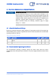
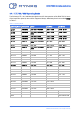
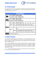
Table 5: Recommended operating conditions.
Symbol
Parameter
Min.
Typ.
Max.
Unit
Vin
Input Voltage on the DC Jack or on the PCB
terminal blocks
18
24
32
V
T
operation
horizontal
The mounting must allow free air circulation
around the heatsink.
DIN-rail is installed vertical causing EDGE FCR 3
heat sink rips to be horizontal
0
-
40
°
C
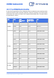
T
operation
vertical
The mounting must allow free air circulation
around the heatsink.
Table Top (Standfuss) is used or the DIN-rail is
installed horizontal causing EDGE FCR 3 heat
sink rips to be vertical (recommended operation
mode)
0
-
60
°
C
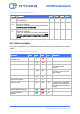
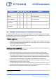
6.3 Power consumption
The power consumptions of the different elements according to the datasheets are listed in
Table 6.
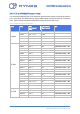
Table 6: Power consumption according to datasheets
Hardware
Min.
Typ.
Max.
Unit
Conditions
Intel Atom E3815 CPU or
derivative CPU
-
4
6.5
W
@1.46 GHz
WI-FI Module
-
1.2
1.9
W
-
GSM Operation
-
1.8
8.25
W
Peak current 2.5 A @GSM,
this mode shall be
avoided.
LTE / 3G Operation
-
1.8
4
W
The typical EDGE FCR 3
operation is with LTE / 3G
data transfer.
Internal Extension Cards
-
0.6
1.1
W
@868 MHz
All other EDGE FCR 3
Electronics together
-
2
3
W
-
Peak Use Case
-
16.5
(20)
W
The EDGE FCR 3 software
measures the temperature
and regulate the maximum
ratings.
Average Allowed Ratings
-
9.6
16.5
W
-
Current measured
@24VDC
-
400
700
mA
-