
Operating Instruction


EDGE FCR 3 Operating Instruction
Rev. C, 2019-09-10 Release Page 37 of 64
© MYNXG Product GmbH, 2019. All rights reserved
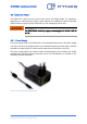
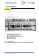
4.1.3 Ethernet Ports
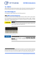
There are two Ethernet ports, indicated as LAN1 and LAN2, designed as RJ45 sockets, and
able to communicate with transfer rates up to 1Gbps. The communication status is displayed
by LEDs at the LAN ports as demonstrated in Table 3.
The ports are working independent and do have fixed TCPIP addresses:
▪ LAN1: IP 192.168.10.10 / Subnet mask 255.255.255.0
▪ LAN2: IP 192.168.11.10 / Subnet mask 255.255.255.0
Table 3: LEDs on Ethernet ports.
LED
Color
Meaning
LED 1
Green
Link Activity
LED 2
Off
10 Mbps Link
LED 2
Green
100 Mbps Link
LED 2
Orange
1000 Mbps Link
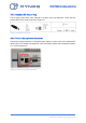
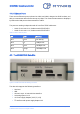
4.2 The EDGE FCR 3 Data Site
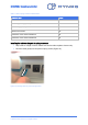
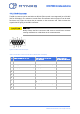
Figure 27: EDGE FCR 3.data site labeling connector
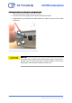
The data side supports the following interfaces:
▪ Sim Card
▪ USB
▪ Current Loop 4 -20 mA with Hart interface
▪ 2x Analog Inputs 0-12 V
▪ 4 x Power supply Outputs (3.3V, 5V, 12V)
▪ I
2
C interface with power supply Output 3.3V