
Operating Instruction


EDGE FCR 3 Operating Instruction
Page 36 of 64 Release Rev. C, 2019-09-10
© MYNXG Product GmbH, 2019. All rights reserved
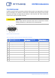
4.1.2 Db-9 Connector
The DB-9 connector can be used either as RS-232 (flow control is not supported) or as RS-485
(half or full duplex). The selection is made from the software and one protocol can be used
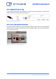
each time only. Figure 26 shows the pin number on the connector and Table 2 shows the
signals that are going to the DB-9 connector.
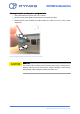
CAUTION
Always fasten the Db-9 connector with screw to avoid loose contacts
causing malfunctions or blackouts in the communication.
Figure 26: DB-9 socket female pins
Table 2: Serial DB-9 connector for RS-232 or RS-485 (half / full duplex)
Pin
Signal name for RS-232
Signal name for RS-485
(Full Duplex)
Signal name for
RS-485 (Half Duplex)
1
Not Connected
Not Connected
Not Connected
2
RXD (input to EDGE FCR 3)
RX+ (input to EDGE FCR 3)
Not Connected
3
TXD (output from EDGE FCR 3)
TO- (output from EDGE FCR 3)
D-
4
Not Connected
Not Connected
Not Connected
5
GND
GND
GND
6
Not Connected
Not Connected
Not Connected
7
Not Connected
TO+ (output from EDGE FCR
3)
D+
8
Not Connected
RX- (input to EDGE FCR 3)
Not Connected
9
Not Connected
Not Connected
Not Connected