
Operating Instruction


EDGE FCR 3 Operating Instruction
Page 26 of 64 Release Rev. C, 2019-09-10
© MYNXG Product GmbH, 2019. All rights reserved
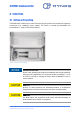
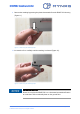
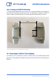
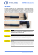
3.2.2 Fastening the EDGE FCR 3 Standings
To ensure that the EDGE FCR 3 stays on place, or for a vertical installation, the standings do
have holes for fastening the device with screws. The drilling plan / distances are shown in
Figure 13 below. Recommended are lens head screws with a shaft diameter of 3.5mm.
Figure 13: Drilling distances for the EDGE FCR 3 standings
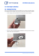
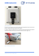
3.3 Device Support by DIN-rail Fixture (Option)
The EDGE FCR 3 can optionally be ordered / delivered with a pre-installed DIN-rail fixture
(Figure 14). This facilitates an installation of the device (inside electronic switch cabinets) on
DIN-rails.
75mm
25mm