
Installation guide
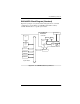

DAC960PRL Block Diagram (SISL)
B-4 AcceleRAID 150 Installation Guide
DAC960PRL Block Diagram (SISL)
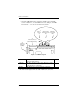
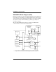
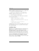
Figure B-2 (example of a system board block diagram) shows the functional
relationship between the Mylex AcceleRAID 150 Controller and the SCSI-
capable system board. The SCSI chip interrupt line(s) are routed to a PCI bus
slot (shaded to indicate SISL availability) specifically preconfigured to
accept the controller.
The non-shaded PCI bus slots indicate an example of available SCSI
connections that are not intended for SISL activity.
Figure B-2. AcceleRAID and SCSI-Capable System Board (SISL)
CPU
PCI Interface
Control
Logic
PCI Bus Slot
PCI Bus Slot
PCI Bus Slot
PCI Bus Slot
SCSI Protocol
Chip
SCSI Protocol
Chip
Te r m .
Te r m .
SCSI Bu
s
SCSI Bu
s
PCI Slot
Pre-configured
for AcceleRAID
System Board
Interrupt Logic
RAID FW NVRAM
Cache Memory
I960RP
AcceleRAID 150
DAC960PRL
Controller
Te r m .
SCSI
Protocol
Chip