
Installation guide

In Case of Problems
3-8 AcceleRAID 150 Installation Guide
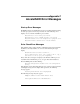
• Check the LED lights when controller is installed. (See the LED
section of Table 2-1, “AcceleRAID Connectors, Jumpers, and LED
Descriptions,” or see the excerpt below for details.)
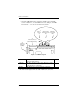
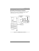
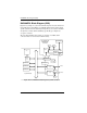
Figure 3-1. LED Descriptions
* The LVD and SE lights will not be ON or OFF at the same time.
U1 LED, ON indicates the controller card failed internal
diagnostics during start-up.
–
LVD (D3) LED, ON = default; the light is always ON unless a single-
ended device is connected. The light will turn OFF when a
single-ended device is detected*.
–
SE (D2) LED, ON indicates a single-ended drive is detected. –
J2
External
Connector
(VHDCI)
JP5
U1
JP1
SE
JP1JP1
JP4
LV D
E
r
r
o
r
o
n
s
e
l
f
t
e
s
t
S
i
n
g
l
e
-
e
n
d
e
d
d
r
i
v
e
i
s
d
e
t
e
c
t
e
d
U1 SE
LV D
L
V
D
d
r
i
v
e
i
s
d
e
t
e
c
t
e
d
J1
Internal Connector
(68-Pin High Density)