
Installation guide

Installation
Manual No. 775020 2-19
Connectors, Jumpers, and LED’s (SISL)
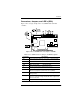
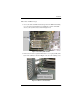
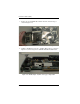
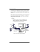
Figure 2-14 is a design example of the AcceleRAID 150 Low Profile
controller.
Figure 2-14. AcceleRAID Connectors, Jumpers, and LED’s
* The LVD and SE lights will not be ON or OFF at the same time.
Table 2-2. AcceleRAID Connectors, Jumpers, and LED Descriptions
Component Description
JP1 Two-pin header available for connection to a front panel LED
that indicates SCSI activity (user supplied).
JP4 Reserved
JP5 Not used
– for maintenance only.
JP10 OFF = Disable SISL ON = Enable SISL
J1 Channel 0 Internal Ultra2 SCSI LVD Connector –
68-Pin High Density Cable
J2 Channel 0 External Ultra2 SCSI LVD Connector –
68-Pin Very High Density Cable Interconnect (VHDCI)
U1 LED, ON indicates the controller failed internal diagnostics
during start-up.
LVD (D3) LED, ON = default; the light is always on unless a single-ended
device is connected. The light will turn OFF when a single-ended
device is detected*.
SE (D2) LED, ON indicates a single-ended drive is detected.