
Installation guide

Installation
Manual No. 775020 2-17
3. Safety check the installation before powering ON the system.
• Make sure cables are properly oriented so that the colored stripe
(Pin 1) on the edge of the ribbon cable aligns with Pin 1 on the
connector (see Figure 2-13).
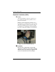
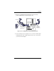
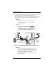
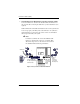
Figure 2-13. SCSI Cable Pin 1 Alignment to the Connector
• Make sure all SCSI conventions (cable type, cable length,
termination, and SCSI addresses) are followed. Examples of cable
types are: flat, rounded, shielded, or non-shielded – use like types
together.
• For information about cable lengths and formats, please refer to
Table A-1 on page A-1.
Pi
n 1
This is a connector on the system board, face up.
Align the colored stripe on the edge of the ribbon
SCSI cable to Pin 1 on the connector.
Note: the colored stripe is Pin 1 in the SCSI cable.