AcceleRAIDTM Installation Guide AcceleRAID 150 (DAC960PRL-1) PCI to Ultra2 SCSI RAID Controller Part Number 775020-02 08P4080 © Copyright 2000 Mylex Corporation. All Rights Reserved. All contents of this manual are copyrighted by Mylex Corporation.
Greetings Thank you for purchasing the Mylex AcceleRAIDTM 150 controller. This manual describes the installation of the Mylex AcceleRAID 150 controller. Requests for technical information about this and other Mylex Corporation products should be made to your Mylex authorized reseller or Mylex sales representative. Please Notice IBM, Mylex, AcceleRAID, DAC960PRL, Global Array Manager, GAM, and RAID EzAssist are trademarks or registered trademarks of International Business Machines Corp.
About This Manual This installation guide covers hardware set-up and configuration procedures necessary for the installation of the Mylex AcceleRAID 150 PCI to Ultra2 SCSI RAID controller. Chapter 1 describes the controller, standard package contents, and usersupplied items necessary for installation. Chapter 2 describes steps to be performed prior to controller installation and the physical installation of the controller. Chapter 3 describes controller board start-up and the BIOS options.
Contents Chapter 1 Introduction Product Description ........................................................................... 1-1 AcceleRAID 150 Controller Features ......................................... 1-3 Operating System Support ................................................................ 1-3 Standard Package Contents ............................................................. 1-4 Hardware .................................................................................... 1-4 Software .....
Operating System Device Drivers ...................................................... 3-6 Global Array Manager (GAM) Server ................................................ 3-6 Global Array Manager (GAM) Client .................................................. 3-6 In Case of Problems .......................................................................... 3-7 Appendix A Installation Notes Helpful AcceleRAID Installation Notes ...............................................
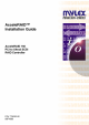
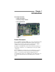
Chapter 1 Introduction This chapter describes: • Product description • Standard package contents • User supplied items Figure 1-1. AcceleRAID 150 Disk Array Controller Product Description The AcceleRAID™ 150 (DAC960PRL-1) is a single-channel PCI-to-Ultra2 SCSI, LVD (Low Voltage Differential) RAID Controller. It has all the functions and performance characteristics of the Mylex line of RAID controllers for several popular network operating systems.
Product Description Mylex’s AcceleRAID 150 can be used in either one of the following two situations: 1. A cost-effective, single-channel, standard PCI RAID controller, which may reside in any PCI slot (to implement a standard RAID connection), or 2. A cost-effective PCI RAID controller with SISL, which must reside in the prewired, SISL-dedicated slot on a system board (to implement a SISL connection).
Introduction AcceleRAID 150 Controller Features Includes the following features: • Ability to operate in an ordinary PCI slot as a single-channel RAID controller in any PCI system. • Ability to add the functionality of an additional RAID SCSI channel which is a Wide Ultra2 SCSI RAID LVD channel (see the note below for further explanation). ☛ Note The AcceleRAID 150 will work as a single-channel, Wide Ultra2 SCSI LVD RAID controller with a system board that has an available PCI slot.
Standard Package Contents Standard Package Contents The following items are supplied with the standard shipping package: Hardware • AcceleRAID 150 Disk Array Controller with documentation included on the CD-ROM and a printed Quick Installation Guide Software • Disk Array Controller Configuration (RAID EzAssist™) utility with documentation on CD-ROM and a printed Quick Configuration Guide • Disk Array Controller Software Kit with documentation on CD-ROM • Software Kit Driver diskettes and a printed PCI Dr
Introduction User-supplied Items The following user-supplied items are required to perform this installation: • Host system with a PCI slot, or • Host system with a prewired SISL supported PCI slot in order to use the SISL feature • SCSI cables to connect SCSI channels to disk drives • Operating system software • Static grounding strap or electrostatic discharge (ESD) safe work area • Disk array enclosure (or equivalent) and SCSI disk drives ☛ Note The supported SCSI drive types include Ultra2 SCSI with L
User-supplied Items 1-6 AcceleRAID 150 Installation Guide
Chapter 2 Installation This chapter describes: • Before you begin • Installation checklist • Connectors, Jumpers, and LED’s • Safety considerations: Caution and Warning notes • Installing the AcceleRAID 1500 controller AcceleRAID 150 with Standard PCI Bus ☛ Note If you will be installing the AcceleRAID 150 controller with the SISL feature, please go to the section titled “AcceleRAID 150 with SISL (SCSI Interrupt Steering Logic)” on page 2-15.
Before You Begin (Standard) Before You Begin (Standard) Installing a standard AcceleRAID 150 PCI to Ultra2 SCSI RAID controller is no more difficult than installing any PCI adapter. Follow these steps and then follow the installation procedures in this chapter. Occasionally, you may need to refer to the instructions that came with your computer system. WARNING Power OFF the system and disconnect the power cord from the electrical wall outlet before opening the system cabinet.
Installation 1. Power OFF the system and any enclosures, such as a tower, and disconnect the power cord and cables before starting the installation. Refer to the instructions provided in your system documentation. Do not disconnect cables or power cords while system power is ON. 2. Read all of the instructions in this chapter completely before proceeding. Follow the Notes, Cautions, and Warnings described in this manual and marked on the equipment. 3.
Standard Installation Checklist Standard Installation Checklist GET READY ☛ Note It is recommended that you wear a grounded wrist strap when working with hardware installation procedures. 1. ____ Decide which available standard PCI slot will be used. 2. ____ Remove the plate from the I/O access port to the PCI slot. 3. ____ Remove the AcceleRAID 150 controller from the anti-static bag. 4. ____ Check Jumper 10 (JP10). If it is installed on the jumper pins, remove it according to Figure 2-6. GET SET 5.
Installation Connectors, Jumpers, and LED’s (Standard) Figure 2-1 is a diagram of the AcceleRAID 150 Low Profile controller. Figure 2-1. AcceleRAID Connectors, Jumpers, and LED’s Table 2-1. AcceleRAID Connectors, Jumpers, and LED Descriptions Component JP1 Description Two-pin header available for connection to a front panel LED that indicates SCSI activity (user supplied). JP4 Reserved JP5 Not used – for maintenance only.
Controller Installation (Standard) Controller Installation (Standard) Caution Anti-static handling procedures are required. Leave the controller in its anti-static bag until it is time to plug it into the PCI slot. Wearing a grounded wrist strap (see Figure 2-2), having the power cord plugged into an electric-ground wall outlet, having the computer power turned off, and following other ESD protective measures are highly recommended.
Installation Follow these installation steps: 1. Choose any available standard PCI slot as shown in Figure 2-3. PC I Slo ts Figure 2-3. Choose an Available PCI Slot 2. Remove the metal cover plate from the slot’s access port (usually at the back of the cabinet). Save the retaining screw as shown in Figure 2-4. . Metal Plate Remove screw to remove metal plate. Save screw to tighten the controller board. Figure 2-4. Remove the Metal Plate Manual No.
Controller Installation (Standard) 3. Remove the AcceleRAID 150 controller from the anti-static bag as shown in Figure 2-5. Figure 2-5. Remove the Anti-static Bag 4. If Jumper 10 (JP10) is installed, place it on only one peg to the OFF position, as shown in Figure 2-6, when using the standard AcceleRAID 150 configuration. JP10 Figure 2-6.
Installation 5. Plug the controller firmly into the selected standard PCI slot as shown in Figure 2-7. System Board Plug Controller into any Available PCI Slot Figure 2-7. Plug Controller into any Standard PCI Slot 6. Use the retaining screw (see Figure 2-4) to tighten the controller by its mounting bracket. The controller will go into the space created when you removed the metal plate. Manual No.
Controller Installation (Standard) 7. Connect the SCSI cables from the disk drives to a SCSI connector on the AcceleRAID 150 controller, as shown in Figure 2-8. (The controller is already connected to the system board.) If necessary, refer to Table A-1 on page A-1 for SCSI formats and bus lengths. ☛ Note In order to ensure an error free environment, the proper cable type designed for a certain SCSI speed must be used.
Installation 8. Termination – Only Internal or External Devices (Standard) Check that the drive channel is properly terminated according to drawings below. The AcceleRAID 150 is equipped with automatic SCSI termination circuitry which handles automatic enabling and disabling of on-board termination. For example, if the controller is at the end of the SCSI bus, it automatically enables on-board termination.
Controller Installation (Standard) 9. Termination – Both Internal and External Devices (Standard) Check that the drive channel is properly terminated according to drawing below. If the controller is in the middle of the SCSI bus, it automatically disables on-board termination.
Installation 10. Remove or set disk drive termination jumpers to the disabled position (if needed). Refer to your system documentation furnished with your disk drives to determine if your termination jumpers need to be adjusted. 11. Set the SCSI ID on the disk drives; ID 7 is reserved for the controller. ☛ Note Each drive must have a unique ID chosen from 0 through 6 or 8 through 15. Be careful not to duplicate a drive address on the same channel.
Controller Installation (Standard) 12. Enable termination power to all the disk drives (usually there is a jumper on the drive). See your device documentation for instructions on how to set your particular disk drive’s termination power and configuration options. ☛ Note The supported SCSI drive types include Ultra2 SCSI with LVD as well as the following single-ended SCSI types: SCSI-1, Fast SCSI, Wide Fast SCSI, Ultra SCSI, Wide Ultra SCSI, and Wide Ultra2 SCSI. 13.
Installation AcceleRAID 150 with SISL (SCSI Interrupt Steering Logic) ☛ Note If you will be installing the AcceleRAID 150 controller as a standard unit without the SISL feature, please go to the section titled “AcceleRAID 150 with Standard PCI Bus” on page 2-1. Caution If an operating system or existing data resides on drives connected to the system board’s resident SCSI channels, a full backup must be performed on these drives prior to this installation. Manual No.
Before You Begin (SISL) Before You Begin (SISL) Installing AcceleRAID PCI to Ultra2 SCSI RAID controller is no more difficult than installing any PCI adapter. Follow these steps and then follow the installation procedures in this chapter. Occasionally, you may need to refer to the instructions that came with your computer system. WARNING Disconnect the system from the electrical wall outlet before opening the system cabinet.
Installation 3. Safety check the installation before powering ON the system. • Make sure cables are properly oriented so that the colored stripe (Pin 1) on the edge of the ribbon cable aligns with Pin 1 on the connector (see Figure 2-13). Pin 1 This is a connector on the system board, face up. Align the colored stripe on the edge of the ribbon SCSI cable to Pin 1 on the connector. Note: the colored stripe is Pin 1 in the SCSI cable. Figure 2-13.
SISL Installation Checklist SISL Installation Checklist GET READY ☛ Note It is recommended that you wear a grounded wrist strap when working with hardware installation procedures. 1. ____ Locate the prewired SISL slot, see your system documentation. 2. ____ Remove the plate from the I/O access port to the SISL PCI slot. 3. ____ Remove the AcceleRAID 150 controller from the anti-static bag. 4. ____ Check Jumper 10 (JP10).
Installation Connectors, Jumpers, and LED’s (SISL) Figure 2-14 is a design example of the AcceleRAID 150 Low Profile controller. Figure 2-14. AcceleRAID Connectors, Jumpers, and LED’s Table 2-2. AcceleRAID Connectors, Jumpers, and LED Descriptions Component JP1 Description Two-pin header available for connection to a front panel LED that indicates SCSI activity (user supplied). JP4 Reserved JP5 Not used – for maintenance only.
Controller Installation (SISL) Controller Installation (SISL) Caution Anti-static handling procedures are required. Leave the controller in its anti-static bag until it is time to plug it into the PCI slot. Wearing a grounded wrist strap (see Figure 2-15), having the power cord plugged into an electric-ground wall outlet, having the computer power turned off, and following other ESD protective measures are highly recommended.
Installation Follow these installation steps: 1. Choose the dedicated PCI slot that was prewired for SISL functionality, (see your system documentation to identify the position of the SISL slot on your system board) as shown in Figure 2-16. PC I Slo ts Figure 2-16. Identify SISL PCI Slot 2. Remove the metal cover plate from the slot’s access port (usually at the back of the cabinet) as shown in Figure 2-17. Save the retaining screw. Metal Plate Remove screw to remove metal plate.
Controller Installation (SISL) 3. Remove the AcceleRAID 150 controller from the anti-static bag as shown in Figure 2-18. Figure 2-18. Remove Controller from the Anti-Static Bag 4. If Jumper 10 (JP10) is not in place, install it (ON position), as shown in Figure 2-19, when using the AcceleRAID 150 with the SISL feature. JP10 Figure 2-19.
Installation 5. Plug the AcceleRAID 150 controller firmly into the dedicated, prewired SISL PCI slot as shown in Figure 2-20. System Board T Channel 0 T Plug Controller into the Specially Wired SISL PCI Slot Wide SCSI Connector on System Board (Ch 1) Narrow SCSI Connector on System Board (Ch 2) Figure 2-20. AcceleRAID 150 in a Typical SISL Installation 6. Use the retaining screw (see Figure 2-17) to secure the controller by its mounting bracket.
Controller Installation (SISL) 7. Connect the SCSI cables from the disk drives to the drive channels, as required, according to the example shown in Figure 2-21. (The controller is already connected to the system board.) If necessary, refer to Table A-1 on page A-1 for SCSI formats and bus lengths. ☛ Note In order to ensure an error free environment, the proper cable type designed for a certain SCSI speed must be used.
Installation 8. AcceleRAID 150 Termination (SISL) Check to confirm that all drive channels are properly terminated as shown in Figure 2-22. The AcceleRAID 150 is equipped with automatic SCSI termination circuitry for the SCSI channel that resides on the AcceleRAID controller. If the controller is at the end of the SCSI bus, it automatically enables on-board termination.
Controller Installation (SISL) 9. SCSI Termination for Embedded System Board Channels (SISL) Correct termination is critical for the SCSI channels. Termination on the end of the bus connecting the disk drives (or other SCSI devices) is required. SCSI termination for the SCSI channels that reside on the system board need to be properly controlled (notice the terminator “T” symbol) as shown in Figure 2-23. You may also want to refer to documentation that was provided with your system.
Installation 10. Remove or set disk drive termination jumpers to the disabled position (if needed). Refer to your system documentation furnished with your disk drives to decide if your termination jumpers need to be adjusted. 11. Set the SCSI ID on the disk drives (ID 7 is reserved for the controller), as shown in Figure 2-24. ☛ Note Each drive must have a unique ID chosen from 0 through 6 or 8 through 15. Be careful not to duplicate a drive address on the same channel.
Controller Installation (SISL) 12. Enable termination power to all the disk drives (usually there is a jumper on the drive). See your device documentation for instructions on how to set your particular disk drive’s termination power and configuration options. ☛ Note The supported SCSI drive types include Ultra2 SCSI with LVD as well as the following single-ended SCSI types: SCSI-1, Fast SCSI, Wide Fast SCSI, Ultra SCSI, Wide Ultra SCSI, and Wide Ultra2 SCSI.
Installation Caution If the SCSI channels embedded on the system board are controlled by a Symbios Logic® chipset, the Symbios BIOS must be disabled in the system BIOS before proceeding with RAID configuration, or with operating system or driver installation. This is to allow the AcceleRAID 150 to take over control of the system board's embedded channels without any conflicts.
Controller Installation (SISL) 2-30 AcceleRAID 150 Installation Guide
Chapter 3 Controller Start-up This chapter describes: • BIOS Options • BIOS Configuration Utility (RAID EzAssist) • Operating System, Device Drivers, GAM • What to Check in Case of Problems This chapter describes the AcceleRAID 150 controller start-up procedures and messages produced by the BIOS during start-up or reboot. This chapter also explains three BIOS options that are available for configuring controller operation.
BIOS Options Setting BIOS Options The available BIOS options are: • BIOS disabled enabled • CD-ROM boot disabled/enabled • 2 GB/8 GB drive geometry BIOS Disable or Enable This option must be enabled in order to toggle the CD-ROM boot and the drive geometry parameters shown in the BIOS Options menu. The CD-ROM BIOS must also be enabled in order to boot from any device (e.g.
Controller Start-up Enable 2 GByte or 8 GByte Drives This setting affects how the BIOS reads the disk drives. Drive geometries can be toggled between 2 GB and 8 GB. The default is 2 GB. When the drive geometry setting is changed, the drive must be low level formatted. Caution Changing this setting after data has been stored will make the data unreadable. If you have already configured your array and have stored data, you should not change this setting.
BIOS Configuration Utility (RAID EzAssist) As a rule of thumb, select 8 GB geometry if the following three cases apply: 1. You have a system (RAID) drive that is greater than 2.145 GB in capacity. 2. The DOS/Windows compatible partitions could be located in an area above the first 2.145 GB. Otherwise the 2 GB option is fine. ☛ Note In the event that the RAID controller needs to be replaced, the current drive geometry will be restored from the configuration on disk (COD).
Controller Start-up Installing the AcceleRAID into an Existing System with a SCSI Boot Device WARNING If an existing operating system is running on a SCSI boot drive using the Symbios Logic SCSI adapter embedded on the system board, the AcceleRAID controller must be installed as the primary (boot) controller.1 You must do the following BEFORE installing the AcceleRAID controller: 1.
Operating System Device Drivers 4. Install the DAC driver for your operating system at the same time you install the operating system itself onto the array, referring to the appropriate chapter of the PCI Disk Array Controller Drivers Installation Guide and User Manual. 5. Reboot and restore your previously backed up data to the array. Operating System Device Drivers Device drivers that are compatible with the controller can be found in the Software Kit.
Controller Start-up In Case of Problems If problems are encountered during start-up, check the following: • Check SCSI cabling for loose connections, pin mismatches (make sure pin 1 on the cable matches pin 1 on the connector), bent pins, and damaged or crossed cables. • Check cable length. This includes internal bus lengths in enclosures. • Check termination. • Check SCSI IDs on all drives. • Remove the system cover, power ON the system and observe the LEDs (see Figure 3-1).
In Case of Problems • Check the LED lights when controller is installed. (See the LED section of Table 2-1, “AcceleRAID Connectors, Jumpers, and LED Descriptions,” or see the excerpt below for details.) Error on self test U1 J1 Internal Connector (68-Pin High Density) J2 External Connector (VHDCI) LVD drive Single-ended drive is detected is detected LVD SE U1 JP1 SE LVD JP4 JP5 Figure 3-1. LED Descriptions U1 LED, ON indicates the controller card failed internal diagnostics during start-up.
Appendix A Installation Notes Helpful AcceleRAID Installation Notes The purpose of this appendix is to provide additional information about your AcceleRAID 150 installation of either the Standard or SISL configuration. There are cross references to direct you to the appropriate topic in the main installation section of this manual. SCSI Formats and Bus Lengths Table A-1. Supported SCSI Formats and Bus Lengths Bus Speed, MB/Sec, Max. Bus Width, Bits Single-ended Low-Voltage Differential Max.
SCSI Cabling for AcceleRAID 150 (Standard and SISL) SCSI Cabling for AcceleRAID 150 (Standard and SISL) An Ultra SCSI or an Ultra2 SCSI channel supports up to 15 SCSI devices. Examples of SCSI devices include hard disk, tape, and CD-ROM. Caution Wide and narrow SCSI cables must not be installed together on any one channel, or the AcceleRAID controller may not work properly. LVD Mode The controller supports Ultra2 SCSI with LVD.
Appendix B AcceleRAID Specifications General Hardware Specifications AcceleRAID Controller DAC960PRL CPU Intel i960 RP® RISC 32-bit microprocessor, 33MHz Memory EDO parity memory 60ns 4 MB or 16 MB Cache Write: Selectable, Write-Through or Write-Back Error Protection: Parity Firmware PCI SCSI ROM Type, Flash EEPROM, 512K x 8 I/O Processor: Embedded in Intel i960 RP microprocessor Transfer Rate: 132 MB/second (burst) I/O Processor: Number of Controller Channels Manual No.
Environmental Specifications Environmental Specifications Controller DAC960PRL Temperature Operating 0°C to +50°C (+32°F to +122°F) Storage -20°C to +60°C (-4°F to +140°F) Operating 10% to 90% relative humidity (non-condensing) Storage 10% to 90% relative humidity (non-condensing) Operating Up to 3,048m (10,000 ft ) Storage Up to 15,240m (50,000 ft) Length: 7.225 inches Width: 4.2 inches Humidity Altitude Form Factor Maximum. Component 0.105 inches solder side Height: 0.
AcceleRAID Specifications DAC960PRL Block Diagram (Standard) Figure B-1 (example of a system board block diagram) shows a standard configuration to use the Mylex AcceleRAID 150 Controller with any available PCI Bus Slot on a capable system board. AcceleRAID 150 DAC960PRL Controller CPU RAID FW Cache Memory NVRAM I960RP PCI Interface Control Logic SCSI Protocol Chip Term. PCI Bus Slot PCI Bus Slot PCI Bus Slot PCI Bus Slot PCI Bus Slot System Board Figure B-1.
DAC960PRL Block Diagram (SISL) DAC960PRL Block Diagram (SISL) Figure B-2 (example of a system board block diagram) shows the functional relationship between the Mylex AcceleRAID 150 Controller and the SCSIcapable system board. The SCSI chip interrupt line(s) are routed to a PCI bus slot (shaded to indicate SISL availability) specifically preconfigured to accept the controller. The non-shaded PCI bus slots indicate an example of available SCSI connections that are not intended for SISL activity.
Appendix C AcceleRAID Error Messages Start-up Error Messages The BIOS looks for any initialization message posted by the firmware during the start-up sequence. If a message is found, one of the following errors displays on screen and the installation process aborts.
Installation Abort During the initialization, if the firmware fails to respond to the BIOS inquiry within two minutes, the following message displays: DAC960Pn not responding--no drives installed. The BIOS then inquires the firmware for its version number and other information, and prints out the following message: DAC960Pn firmware version x.
AcceleRAID Error Messages NVRAM Error With Firmware 4.x, if the BIOS displays a mismatch between the NVRAM and the COD, no drives will be installed. Normally this error will not be displayed. If it is, boot and run the RAID EzAssist (previously BIOS) Configuration Utility (see “BIOS Configuration Utility (RAID EzAssist).” to recover from the error.
System Reboot or Power Down C-4 AcceleRAID 150 Installation Guide
Appendix D Enclosure Management Introduction Mylex’s AcceleRAID controllers support the industry standard enclosure management protocol SCSI Accessed Fault-Tolerant Enclosures (SAF-TE). This feature allows the host to monitor drive enclosures and detect certain faults or operating environment conditions. The host can make a decision to shut down the system or issue a warning based on the type of fault detected.
SAF-TE D-2 AcceleRAID 150 Installation Guide
Appendix E Regulatory Information Class B Compliance THIS DEVICE COMPLIES WITH PART 15 OF THE FCC RULES. OPERATION IS SUBJECT TO THE FOLLOWING TWO CONDITIONS: 1. THIS DEVICE MAY NOT CAUSE HARMFUL INTERFERENCE, AND 2. THIS DEVICE MUST ACCEPT ANY INTERFERENCE RECEIVED, INCLUDING INTERFERENCE THAT MAY CAUSE UNDESIRED OPERATION. All external connections should be made using shielded cables.
Declaration of Conformity Declaration of Conformity Per FCC Part 2, Section 2.1077(a) Manufacturer’s Name: Mylex Corporation Manufacturer’s Address: 34551 Ardenwood Blvd. Fremont, CA 94555-3607 USA Declares that the product: Product Name: AcceleRAID 150 Ultra2 SCSI RAID Controller Model Number(s): DAC960PRL-1 Year of Manufacture: 1998 Conforms to the following Product Specification(s): FCC: CFR 47 Part 15, Subpart B, Section 15.107(e) and Section 15.109(g) Class B Digital Device tested per ANSI C63.
Regulatory Information Declaration of Conformity Per 89\336\EEC Responsible Party Name: Mylex Corporation Address: 34551 Ardenwood Boulevard Fremont, CA 94555-3607 USA hereby declares that the product Trade Name: Model Number: AcceleRAID 150 Ultra2 SCSI RAID Controller DAC960PRL-1 conforms to the following specifications Standards: EN 50081-1:1992, EMI EN 55022 Class B (Radiated), Class B (Conducted) EN 50082-1:1992, Immunity EN 61000-4-2:1995 Electrostatic Discharge EN 61000-4-3:1996 Radiated Suscept
Community of Europe Community of Europe CE mark is rated for the AcceleRAID 150 Ultra2 SCSI RAID Controller as follows: CISPR 22 Radiated Emission EN55022, EN5082-1 Generic immunity standard for the following: IEC 801-2 ESD, IEC 801-3 Radiated, and IEC 801-4 EFT/Burst Warning! This is a Class B product. In a residential environment this product may cause radio interference, in which case the user may be required to take adequate measures. Achtung! Dieses ist ein Gerät der Funkstörgrenzwertklasse B.
Regulatory Information Underwriters Laboratories Manual No.
Underwriters Laboratories E-6 AcceleRAID 150 Installation Guide
Glossary AcceleRAID™ The AcceleRAID family features high performance, cost effective Ultra SCSI/Ultra2 SCSI LVD and Ultra 160 SCSI to PCI RAID controllers and adapters for high-end desktops, workstations, and entry level and mid range servers. AcceleRAID controllers support PCI-based motherboards with embedded SCSI chips and systems that have a PCI expansion slot designated for add-in RAID controllers. The AcceleRAID family consists of the 150, 200, 250, 352, 160, 170, and 170LP controllers.
Automatic Rebuild Mylex controllers provide automatic rebuild capabilities in the event of a physical disk drive failure. The controller performs a rebuild operation automatically when a disk drive fails and both of the following conditions are true: A standby or hot spare disk drive of identical or larger size is found attached to the same controller; All system drives that are dependent on the failed disk drive are configured as a redundant array: RAID 1, RAID 3, RAID 5, or RAID 0+1.
Glossary Bus A set of conductors that connect the functional units in a computer and are the channels through which data is transferred. There are several types of bus channels, including serial, parallel, PCI, ISA, EISA, and MCA. See also I/O Bus. Cables The physical wires (copper or fibre optic) over which electrical signals are transmitted. Cables are used to connect peripherals (such as disk arrays) to computers and servers or to connect peripherals or components to each other.
SCSI bus on a disk array controller. Each disk array controller provides at least one channel. Conservative Cache An operating mode in which system drives configured with the write-back caching policy are treated as though they were configured for write-through operation and the cache is flushed. Consistency Check A process that verifies the integrity of redundant data.
Glossary Disk Array A collection of disks from one or more commonly accessible disk systems. Disk arrays, also known as RAID, allow disk drives to be used together to improve fault tolerance, performance, or both. Disk arrays are commonly used on servers and are becoming more popular on desktops and workstations. See also Array. Disk Drive A device for the electronic digital storage of information. Disk System A storage system capable of supporting only disks.
ECC Error Correcting Code, a method of generating redundant information which can be used to detect and correct errors in stored or transmitted data. EDO Extended Data Output, a type of random access memory (RAM) chip designed to improve the time to read from memory on faster microprocessors such as the Intel® Pentium. EEPROM Electrically Erasable PROM, see EPROM.
Glossary Failback Restoring a failed system component’s share of a load to a replacement component. Failover A mode of operation for failure tolerant systems in which a component has failed and a redundant component has assumed its functions. Failover Port A fibre channel port capable of assuming I/O requests for another, failed port on the loop. During normal operation, a failover port may be active or inactive. Failover ports assume the same loop ID and, optionally, the same node from the failed port.
Gigabyte 230 (1,073,741,824) bytes. Abbreviated as G or GB. Global Array Manager (GAM) A Mylex RAID management utility that allows a system administrator to configure, monitor, and manage network RAID storage from anywhere in the world. GAM can communicate critical notification via e-mail, fax, pager, SNMP or the launching of an application. GAM is everything needed to manage Mylex PCI RAID Controllers, SCSI Host Adapters, and External RAID Controllers.
Glossary controller to “rebuild” the data on the new drive, all without interrupting system operations. Once the rebuild is complete, the controller will be brought back into a fault tolerant state. See also Hot Swap. Hot Spare A physical disk drive not part of a system drive that the controller can use to automatically rebuild a critical system drive. The hot spare drive must have at least as much capacity as the largest disk drive in the array or the rebuild may not start. See also Hot Standby.
I/O Input/Output, the transmission of information between an external source and the computer. I/O Bus Any path used for the transfer of data and control information between I/O adapters and storage controllers or storage devices. See also Bus. I2O Intelligent Input/Output, a driver that uses special I/O processes to eliminate I/O bottlenecks. The processes deal with interrupt handling, buffering, and data transfer.
Glossary Logical Drive States A logical (system) drive can be Online, Critical, or Offline. Notice that the term “online” is used for both physical and logical drives. LVD Low Voltage Differential, a form of SCSI signaling introduced with Ultra2 SCSI (Fast40 SCSI) uses data high and data low signal lines to increase transmission distances over those of single-ended (conventional SCSI signaling) lines. LVD allows for cable lengths of up to 12 meters (approximately 39 feet) with up to 15 devices.
Mirroring Refers to the complete duplication of data on one disk drive to another disk drive, this duplication occurs simultaneously with each write operation: each disk will be the mirror image of the other (also known as RAID Level 1, see RAID levels). All Mylex RAID controllers support mirroring. M.O.R.E. Mylex Online RAID Expansion, an advanced configuration mode that allows expansion of any unconfigured or hot spare drive into the expandable drive group while the controller is online with the host.
Glossary Offline A Logical Drive is in an “offline” state if no data can be read from it or written to it. Offline does not apply to physical disk drives. System commands issued to offline logical drives are returned with an error status; no operations can be performed on offline logical drives. See also Logical Drive States, Online, and Critical. Online A Logical Drive is in an “online” state if all of its participating SCSI drives have power and are operational.
Physical Device Any device connected to some kind of hardware. For example, SCSI disk, fibre disk, network disk, RAM disk, etc. Physical Disk Drive A single hard disk drive. Each physical disk drive is assigned a unique identification address. PROM Programmable Read-Only Memory, memory that users with appropriate instructions can reprogram. Protocol A special set of rules for transmitting data between two devices in a telecommunication connection.
Glossary RAID Levels Mylex disk array controllers support four RAID Advisory Board approved (RAID 0, RAID 1, RAID 3, and RAID 5), two special (RAID 0+1, and JBOD), and three spanned (RAID 10, 30, and 50) RAID levels. All DAC960, AcceleRAID, and eXtremeRAID series controllers support these RAID levels. Level 0: Provides block “striping” across multiple drives, yielding higher performance than is possible with individual drives. This level does not provide any redundancy.
RAID Migration A feature in RAID subsystems that allows for changing a RAID level to another level without powering down the system. RAM Random Access Memory, the "built-in" readable and writable data storage that comes with (or can be added to) a computer. RISC Reduced Instruction Set Computing, architecture for an application-specific processor. RJ-11, RJ-45 Registered Jacks (sometimes described as RJ-XX), a series of telephone connection interfaces (receptacle and plug) that are registered with the U.
Glossary enclosure itself is treated as simply another device on the SCSI bus. Many other leading server, storage, and RAID controller manufacturers worldwide have endorsed the SAF-TE specification. Products compliant with the SAF-TE specification will reduce the cost of managing storage enclosures, making it easier for a LAN administrator to obtain base-level fault-tolerant alert notification and status information. All Mylex RAID controllers feature SAF-TE.
Offline: A SCSI disk drive is in a “offline” state if it is not present, if it is present but not powered on, or if it failed to operate properly and was “offline” by the controller. When the controller detects a failure on a disk, it “kills” that disk by changing its state to “offline.” An “offline” SCSI drive can also be present and powered on, but a SCSI drive in a “offline” state does not participate in any I/O activity; no commands are issued to dead drives.
Glossary reported, conservative cache is enabled and all system drives are switched to write-through cache. Primarily used in fibre enclosures. SIMM Single In-line Memory Module, RAM packed on a small circuit board with a defined edge connector. Two SIMMs are required for a 64-bit memory path on a Pentium processor. See also DIMM. SISL See SCSI Interrupt Steering Logic (SISL).
To use the standby rebuild feature, you should always maintain a standby SCSI disk in your system. When a disk fails, the standby disk will automatically replace the failed drive and the data will be rebuilt. The system administrator can disconnect and remove the bad disk and replace it with a new disk. The administrator can then make this new disk a standby. The standby replacement table has a limit of 8 automatic replacements in any session (from power-on/reset to the next power-off/reset).
Glossary drive 1, block 2 on SCSI drive 2, block 3 on SCSI drive 3, block 4 on SCSI drive 1, block 5 on SCSI drive 2, and so on. This storage method increases the disk system throughput by ensuring a balanced load among all drives. Sustained Data Transfer Rate A rate of data transfer defined for continuous operation at a maximum speed level.
Ultra SCSI (Fast 20 SCSI) A high performance SCSI protocol that has a bus speed of 20 Megabytes per second in the Narrow SCSI configuration and 40 MB in the Wide SCSI (Fast 20 Wide SCSI) configuration. Ultra Wide SCSI 16-bit wide Ultra SCSI (IS devices), double the speed of narrow SCSI. Ultra2 SCSI (Fast 40 SCSI) A higher performance SCSI protocol than Ultra SCSI.
Index A D Aborted Installation C-2 AcceleRAID 150 SCSI Interrupt Steering Logic (SISL) 1-1 SISL (SCSI Interrupt Steering Logic) 2-15 Standard PCI Bus 2-1 Alignment of Pin 1 and cables 2-3, 2-17 Anti-static bag 2-8, 2-22 Anti-static handling procedures 2-6, 2-20 Automatic circuitry 2-11, 2-25 DAC960PRL Block Diagram (SISL) B-4 (Standard) B-3 Default BIOS geometry 3-3 Default for CD-ROM option 3-2 Disabled on-board termination 2-12, 2-25 Disposal of lithium battery/crystal module 2-2, 2-16 Drive channel(s)
G N General hardware specifications cache B-1 CPU B-1 firmware B-1 memory B-1 PCI B-1 SCSI B-1 transfer rate B-1 Nonvolatile RAM (NVRAM) 2-2, 2-16 Number of devices allowed A-1 NVRAM error C-3 I I/O Processors Intel i960 RP B-1 Symbios 53C895 B-1 In case of problems 3-7 Installation 2-1 SISL 2-15 Standard 2-1 Installation Checklist SISL 2-18 Standard 2-4 Intel boards N440BX, T440BX 1-2 NA440BX, NC440 1-2 SC450NX 1-2 Internal connector 2-11, 2-25 Internal drive configuration 2-11 Internal/external drive
Standard Configuration LVD mode A-2 SCSI cabling A-2 Single-ended mode A-2 Standard PCI slot 2-4, 2-7 Symbios 53C895 B-1 System reboot C-3 T Termination - Both Internal and External Devices (SISL) 2-25 Termination - Both Internal and External Devices (Standard) 2-12 Termination - Embedded System Board Channels (SISL) 2-26 Termination - Only Internal or External Devices (Standard) 2-11 Termination disabled 2-12, 2-25 Termination enabled 2-11, 2-25 Troubleshoot, in case of problems 3-7 U Ultra2 SCSI channel
Index-4 AcceleRAID 150 Installation Guide
DAC960 Problem Report Customer Identification DACPRL-1 Name: ___________________________________ Company: ________________________________ Address: _________________________________ ________________________________________ ________________________________________ Country: _________________________________ Phone Number:____________________________ Fax Number:______________________________ DACPRL-1 Identification Date: Purchase Date: Model Invoice Number: Serial Number: # Chnls: Cache: Firmware Ver: BIOS Ver
Mylex Warranty - Customer Policy Thank you for purchasing this Mylex product for your computer system. In addition to this high-quality product, your purchase entitles you to the warranty coverage set forth herein. In order to provide this warranty coverage, and to indicate your acceptance of this warranty, we must have the attached Warranty Registration Card completed and returned to us within 15 days of your purchase.
Returned Merchandise Procedures If you suspect that there is a defect in the material or workmanship of this PRODUCT, you should contact the person or company from which you purchased it. That person or company may be able to solve the problem and if not, will be able to contact us for technical assistance or repair. If it is determined that the PRODUCT must be returned to MYLEX for repair or replacement, contact MYLEX’s Technical Support Department at 510-608-2400 before it is returned.