
Instruction manual


8.0 Maintenance Guide
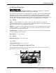
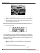
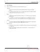
Gib Screws
Nylon Guide
Screws
Figure 35
5. Tighten the bottom, nylon guide screws until they just touch the guide. Do not overtighten or
they could cause the backgauge to bind.
6. Similarly, turn the side gib screws in until they just touch the guide. Lock in position with the
jam nuts.
7. Run the backgauge back and forth the length of the table using the backgauge glide control.
Check for any binding. Readjust if necessary.
NOTE: The screws should be tightened to hold the backgauge square against the guide rail.
Excessive tightening will cause the backgauge to bind and cause premature wear of all components.
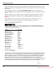
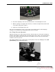
8.4.3 Squaring the Backgauge
Figure 36
To test if the backgauge is square, place a small lift of paper against the left side of the backgauge
(but not against the side guide) and make a cut. Now, leave the backgauge in the same position, flip
the lift over and push it against the right side of the backgauge (but not against the side guide). Make
another cut to see if any of the paper will trim off. Run two checks, one starting on the left and
moving to the right; the other, moving from the right to the left. If paper is trimmed in either sequence,
the backgauge is out of square.
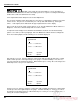
1. Make sure the backgauge gibs are set properly (see section 8.4.2 ).
NOTE: Gib adjustments are not necessary on initial machine set-up as gibs have been
adjusted at the factory.
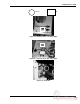
2. Remove the rear plexiglass table cover.
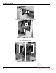
3. Loosen the jam nuts on the backgauge adjusting screws (Figure 37).
46