
Manual

5
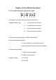
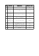
Serial
Communication
Interface
1:5V 2:TX 3:RX 4:GND
1.25mm-4P
6
CAN_H / A
CAN Communication / 485
Communication (optional
)
Pad
7
CAN_L / B
CAN Communication / 485
Communication (optional
)
Pad
8
Power Supply
24V-48V
Pad
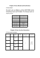
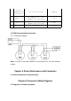
3.4 CAN Communication Connection
3.4.1. Schematic Diagram
Note: The end of the motor needs to be connected to a 120 ohm terminal
resistor
Chapter 4 Driver Maintenance and Precautions
4.1 Driver maintenance and precautions
Chapter 5 Common Problem Diagnosis
5.1 Diagnosis of common problems
Main Control
Motor 1
Motor 2
Motor N