
RMD-S Series Servo Actuator User Manual Rev 1.01 (Release) (1)
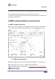
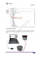
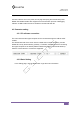
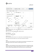
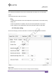
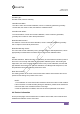
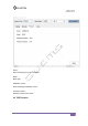
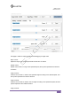
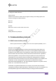
Table Of Contents

RMD-S series
DOC Rev V1.01
1
1
3.5.2 Bus terminal resistance setting (4th bit of DIP switch)
T
h
e
4
t
h
b
i
t
O
N
i
n
d
i
c
a
t
e
s
t
h
a
t
t
h
e
b
u
s
t
e
r
m
i
n
a
l
r
e
s
i
s
t
a
n
c
e
(
1
2
0
Ω
)
i
s
O
N
,
*Generally, the last node of CAN bus needs to be connected with terminal resistance (the
4th bit is set to ON position)
4
R
M
D
c
o
n
f
i
g
I
n
s
t
a
l
l
a
t
i
o
n
a
n
d
p
a
r
a
m
e
t
e
r
4
.
1
R
M
D
c
o
n
f
i
g
B
r
i
e
f
I
n
t
r
o
d
u
c
t
i
o
R
M
D
-
L
c
o
n
f
i
g
i
s
a
P
C
d
e
b
u
g
g
i
n
g
t
o
o
l
d
e
v
e
l
o
p
e
d
b
y
G
u
a
n
g
y
u
m
e
c
h
a
n
i
c
a
l
a
n
d
E
l
e
c
t
r
i
c
a
l
C
o
.
,
L
t
d
.
,
w
h
i
c
h
c
a
n
b
e
u
s
e
d
o
n
c
o
m
p
u
t
e
r
s
a
b
o
v
e
w
i
n
7
.
T
h
e
o
p
e
r
a
t
i
o
n
i
n
t
e
r
f
a
c
e
i
s
a
s
f
o
l
l
o
w
s
:
4
.
1
.
1
R
M
D
c
o
n
f
i
g
I
n
s
t
a
l
l
a
t
i
o
n
R
M
D
c
o
n
f
i
g
i
n
s
t
a
l
l
a
t
i
o
n
i
s
t
h
e
s
a
m
e
a
s
w
i
n
d
o
w
s
g
e
n
e
r
a
l
a
p
p
l
i
c
a
t
i
o
n
,
J
u
s
t
d
o
u
b
l
e
c
l
i
c
k
t
h
e
i
c
o
n
t
o
s
t
a
r
t
,
I
n
s
t
a
l
l
p
a
t
h
s
e
l
e
c
t
d
e
f
a
u
l
t
p
a
t
h
.
R
M
D
c
o
n
f
i
g
I
n
s
t
a
l
l
a
t
i
o
n
f
i
l
e
d
o
w
n
l
o
a
d
a
d
d
r
e
s
s
:
h
t
t
p
:
/
/
w
w
w
.
g
y
e
m
s
.
c
n
/
s
u
p
p
o
r
t
/
d
o
w
n
l
o
a
d