RMD-S series DOC Rev V1.01 RMD-S Series Servo Actuator User Manual contents 1 PRODUCT INTRODUCTION............................................................................................................ 2 1.1 NAMING RULES...............................................................................................................................3 1.2 FEATURES....................................................................................................................................... 3 1.2.
RMD-S series DOC Rev V1.01 3 HARDWARE CONNECTION............................................................................................................ 7 3.1 INTERFACE EXPLAINING.................................................................................................................. 7 3.3 POWER AND COMMUNICATION INTERFACE.................................................................................... 9 3.4 BUS CONNECTION DIAGRAM.............................................................
RMD-S series DOC Rev V1.01 Main application: Robotic arm Manipulator Screw drive 3D printer Gimbal Turntable Inspection robot 1.1 Naming Rules 1.2 Features Programmable and integrated servo motor Working voltage DC 12-24V 1.2.1 control mode Open loop control mode Velocity control mode Position control mode 1.2.2 Communication control mode RS485 Bus communication for control optional CAN Bus communication for control optional 1.2.
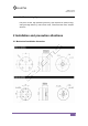
RMD-S series DOC Rev V1.01 1.2.4 Technical highlight Fully servo control, high positioning accuracy, high response for speed, energy saving and high efficiency, multi control mode , smooth and low noise, compact structure 2 Installation and precaution attentions 2.
RMD-S series DOC Rev V1.
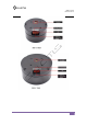
RMD-S series DOC Rev V1.01 Attentions: Enough space shall be reserved for motor I / O interface. Suggestions: >20mm The length of the installation screw shall meet the requirements of the drawings. If it is too long, the internal structure will be damaged, and if it is too short, there is a risk of loosening. Warning: Please carefully read and follow the requirements in this manual. It can help you set up and operate the driver correctly and achieve the best performance.
RMD-S series DOC Rev V1.01 observed: Connection and environmental conditions specified in the product technical data and technical requirements for all other connected components. Only when the product meets the requirements of the product specification, it is allowed to operate the product according to the relevant safety regulations. Follow the instructions and warnings in this document.
RMD-S series DOC Rev V1.
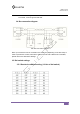
RMD-S series DOC Rev V1.01 3.3 Power and communication interface Note: 1. Power and communication interface type:S6B-ZR-SM4A-TF; 2.For AUX1,AUX2,it is independent of the motor drive circuit from one plug to another. It is a straight line on the PCB, which can be left for the user to use. If it is not used, it can be ignored and float. Note: 1. Power and communication interface type:S8B-ZR-SM4A-TF; 2.
RMD-S series DOC Rev V1.01 another. It is a straight line on the PCB, which can be left for the user to use. If it is not used, it can be ignored and float. 3.4 Bus connection diagram Can bus connection diagram Note: up to 32 drivers can be mounted on the same bus (depending on the bus load). In order to prevent bus conflict, each driver needs to be set with a different ID. for details, please refer to the dial switch settings. 3.5 Dial switch settings 3.5.
RMD-S series DOC Rev V1.01 3.5.2 Bus terminal resistance setting (4th bit of DIP switch) The 4th bit ON indicates that the bus terminal resistance (120 Ω) is ON, *Generally, the last node of CAN bus needs to be connected with terminal resistance (the 4th bit is set to ON position) 4 RMD config Installation and parameter 4.1 RMD config Brief Introductio RMD-L config is a PC debugging tool developed by Guangyu mechanical and Electrical Co., Ltd., which can be used on computers above win7.
RMD-S series DOC Rev V1.01 4.1.2 Connection tool and drive installation RMD-S also has the function of connecting RMD config software. Install the driver of the tool before use. A USB to RS485 converter is required for connection, as shown in the following figure: Windows Driver download address:http://www.gyems.cn/support/download After the download is completed, unzip, double-click to start the installation until it is finished.
RMD-S series DOC Rev V1.01 4.
RMD-S series DOC Rev V1.01 Pay attention to: Connect and then turn on the power, do not plug and unplug the terminal with power. RS485 The RS485 interface also supports the communication protocol of debugging software. A USB to 485 converter is needed to communicate with PC. 4.3 Parameter setting 4.3.1 PC software connection The motor drive and the upper computer can be connected through the USB to UART module.
RMD-S series DOC Rev V1.01 Driver ID: Set the address number of the motor. When the value is 0, the address code of the dial switch takes effect; When it is not 0, the value set is the motor address number Driver Baudrate: Set the baud rate of the driver. Shutdown Time: Set the shutdown time of the motor. If no control order is received during this time, the power will be shut down; When set to 0, the motor will never be turned off. Angle: Angle loop control parameters.
RMD-S series DOC Rev V1.01 Acceleration The maximum acceleration of the motor is limited. When the value is 0, it is not limited Power : Limits the final power output to the motor. Note: 1. The actual acceleration of the motor depends on PI parameters, motor load, driving voltage, etc. 2. After the parameter is modified, click write to save the parameter to the driver. 3. After setting, the new parameters need to be powered on again to take effect. 4.3.
RMD-S series DOC Rev V1.01 Encoder Type: Encoder model, which is read-only. Motor/Encoder Ratio: The ratio of motor and encoder calibration, which is a read-only parameter, generally around 1000, the closer to 1000, the better the calibration effect. Motor/Encoder Offset: The zero deviation of motor and encoder calibration, which is read-only parameter, generally has no effect on motor drive performance.
RMD-S series DOC Rev V1.01 Driver : Driver board type for motor installation Motor : Motor type Hardware version : Driver board type hardware version Firmware version : Software version of the driver 4.
RMD-S series DOC Rev V1.
RMD-S series DOC Rev V1.01 Position control mode 3, rotate to the specified angle at the specified speed, and reverse to change the rotation direction Angle control4: Position control mode 4, rotate to the set angle according to the setting speed, and reverse to change the rotation direction Motor off: Motor off Encoder: Returns the current encoder value of the motor Command: Display data sent by serial port 5. Communication protocol 5.