Standard APC45 Programmable Paper Cutter Instruction Manual Provided By http://www.MyBinding.com http://www.MyBindingBlog.
PAPER CUTTER APC- 45 Important Information • This manual is designed to help you to install, operate and maintain the APC-45 Paper Cutter. Please read and understand this manual, and keep it in a safe and convenient place. • Do not operate the APC-45 until you read and understand the instructions in this manual. • Horizon International Inc.
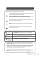
Safety Precautions Safety precautions are indicated in this manual as follows: The term WARNING indicates a potentially hazardous situation which, if not avoided, could result in death or serious injury. The term CAUTION indicates a potentially hazardous situation which, if not avoided, may result in serious injury, or damage to the machine. This symbol indicates a note which includes important information. Follow the note to operate the machine safely. This symbol indicates a prohibited action.
Safety Operation Precautions WARNING for Operation This machine must be operated by just one person at a time. Various safety devices are installed on this machine. If any of these are bypassed or removed, this may cause severe accident and personal injury. Each operator should be familiar with the safety instructions, be aware of the potential dangers, and have sufficient knowledge of how to manage an accident. Anyone who does not have this training should not operate the machine.
CAUTION for Installation Make sure to connect the ground wire. Ground Terminal Make sure to connect the accessory ground wire. If the ground wire is not connected, the letters on the guide window may not appear correctly. Space Required for Installation As the electrical parts are installed on the lower left of the machine, repair work may be done from the right side. Allow about 600 to 700 mm (23.7 to 27.6") on the left side of the machine if it is possible.
CONTENTS Important Information ........................................................................................ I Safety Precautions ............................................................................................ II Safety Operation Precautions ......................................................................... III 1. Machine Descriptions .................................................................................. 1 1-1 Machine Descriptions ..................................
This page is intentionally left blank.
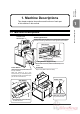
Machine Descriptions 1. Machine Descriptions Machine Descriptions This chapter explains the positions and functions of each part of this machine in this manual. 1-1 Machine Descriptions Control Panel See next page. Beam Light Sensors Cutting motion does not start even if pressing both cutting buttons when the invisible light between the beam light sensors is blocked. Knife Cover Side Guide Cutting Stick Cutting Buttons (Upper Inside) These buttons must be pressed simultaneously to cut sheets.
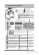
1-2 Control Panel Descriptions Control Panel When pressing once, moves by 0.1 mm (0.005”) Backgauge Backward Backgauge Forward When continuing to press, moves at a low speed. When continuing to press more than three seconds, moves at a high speed. Numeric Keypad: The input value appears in the guide window. Current Position of the Backgauge C Clear = The input value is cleared. Ent Enter = The input value is entered. Guide Window M1 M2 Three programs can be stored.
Machine Descriptions 1-3 Cutting Mechanism 3 Knife Holder After the clamp presses the sheets, this knife holder lowers and the sheets are cut. Knife Cover Clamp M 2 Foot Pedal Clamp When the foot pedal (No.7) is stepped, only this part lowers. Knife Cutting Mechanism 4 1 When the cutting buttons are pressed, this clamp presses the sheets first. 5 Cutting Stick The knife cuts into this stick and the sheets are cut. If the groove of the cutting stick becomes deep, turn it by 90 degrees.
This page is intentionally left blank.
Safety Checks 2. Safety Checks This chapter explains how to check the safety functions before starting the cutting operation. 2-1 Check the Power Switch WARNING If you notice a problem while making the safety checks, do not try to correct the problem by yourself. If the machine is not working correctly, it may cause severe personal injury. Please notify your local dealer. Guide Window (1) Horizon ROM Version appears. APC-45 VX.XX (2) Horizon LOADING . . .
2-1 Check the Power Switch Check the current position of the backgauge. - If the value “400.0” appears in the current position box and guide window, the power switch and the software are OK. 400.
In the following steps, if the machine does not operate as explained “the machine is OK”, stop the check immediately. Press both cutting buttons continuously. - The cutting process is as follows: 1. The clamp lowers. Turn on the power switch. 2. The knife lowers. - When the initialization is completed, the current position value (=400.0) appears. 3. The knife lifts. Safety Checks 2-2 Check the Cutting Buttons 4. The clamp lifts. Keep pressing both cutting buttons after the cutting process.
2-3 Check the Beam Light Sensors Turn on the power switch. Press both cutting buttons. - When the initialization is completed, the current position value (=400.0) appears. - Continue to press the cutting buttons while the obstacle is on the table. - If the clamp and the knife do not move, the machine is OK. Check the beam sensor. - If the LED on the receiver on the right sensor illuminates red, the machine is OK.
2-4 Check the Control Panel button. Check the Control Panel Press the Safety Checks In the following steps, if the machine does not operate as explained “the software is OK”, stop the check immediately. - Press the button once and release. Continue to press the button. - If the value of the current position of the backgauge decreases by 0.1 mm (0.005”), the software is OK.
2-5 Check the Foot Pedal In the following steps, if the machine does not operate as explained “the machine is OK”, stop the check immediately. The foot pedal is used for the following purpose. 1. To check the cutting position The cutting position can be checked before actual cut by stepping on the foot pedal and lowering the clamp. 2. Sheet Press Swelled or curled sheets can be cut more accurately by stepping on the foot pedal and pressing them by the clamp.
3. Operation Procedures Cutting Operation Cutting the sheets by aligning them to the present cutting line on the Cutting Line (light shows the cutting line). 2 Cutting Operation by Entering a Value Cutting the sheets by entering a value directly or positioning using the backgauge forward and backward buttons. 3 Cutting Operation by Programmed Value Program a complicated cutting process beforehand and cutting the sheets by recalling the program.
3-1 Cutting Operation on the Cutting Line Align the desired cutting position with the cutting line. Press both cutting buttons at the same time and keep pressing them. - Align the desired cutting position with the cutting line by pressing the backgauge forward button. - The cutting operation starts. - Release your hands from the cutting buttons when the knife returns to the upper limit. Align the cutting position by moving the backgauge forward.
3-1 Cutting Operation on the Cutting Line Remove the cut sheets. Operation Procedures - The value of the cutting length appears in the box of the current position of the backgauge. If you memorize this value, the sheets can be cut for the same length at the next time. - If the button is pressed, the cut sheets is pushed forward. (The cutting position changes. If you memorizes the value, input the value using the numeric keypad. The backgauge moves to the set position.
3-2 Cutting Operation by Entering a Value This section explains the cutting operation when entering a value directly without using program. WARNING This machine must be operated by just one person at a time. CAUTION Do not cut anything besides paper. This may damage the machine. Press the button. - The LED on the upper left of this button is illuminated and shows that the “cutting operation by entering a value” is selected. LED Guide Window Input the cutting length. - Input using the numeric keypad.
3-2 Cutting Operation by Entering a Value - When the automatic push-out mode is selected, the backgauge moves forward after every cutting to push the sheets forward. - Press the button. The icon of the "Auto- Press both cutting buttons at the same time and keep pressing them. - The cutting operation starts. - Release your hands from the cutting buttons when the knife reaches the lower limit and starts to lift. matic Push-Out Mode" appears on the guide window.
3-2 Cutting Operation by Entering a Value Enter the value of the cutting length for the next cutting. - Repeat from the step . - If the cutting operation is finished, remove the cut sheets. - If the button is pressed, the cut sheets on the rear side move forward. The movement of the backgauge when it moves backward for positioning: (Example) If the sheet is cut to 200.0 mm (11.000”) and next cut to 300.0 mm (14.000”), the backgauge moves backward to the position of 307.0 mm (14.
3-3 Cutting Operation by Programmed Value WARNING This machine must be operated by just one person at a time. Input the course number. - Input using the numeric keypad. Example: When recalling the course number 3, press the 3 and Ent keys. The job name of the course number should be written down when programming. To check the process of the course, press the CAUTION Do not cut anything besides paper. This may damage the machine. button.
3-3 Cutting Operation by Programmed Value Place the sheets. - The maximum cutting height is 60 mm (2.36”). - Arrange the sheets by aligning them with the backgauge and side guide. Do not pile the narrow sheets high. Place the sheets on the other side so that the clamp does not incline widely. - When the step 1 is completed, the backgauge pushes out the sheets for 50 mm (2”) and moves to the position of the step 2.
3-3 Cutting Operation by Programmed Value Repeat the cutting operation in the same way. COURSE : 3 8:50.0 8/8 If nothing appears here, the backgauge moves to the position of the step 1. Cutting Operation by Programmed Value Last Cutting Step Operation Procedures - When the last cutting step is completed, the backgauge moves to the position of the step 1 automatically.
3-4 Function Cutting This section explains how to recall the cutting job performed most frequently using the function keys M1 through M3. Three programs can be saved. Call the service representatives of your local dealer. WARNING This machine must be operated by just one person at a time. CAUTION Do not cut anything besides paper. This may damage the machine. Write down your own program value for your reference. M1 M2 M3 The following steps explain the function cutting using the key.
3-4 Function Cutting Perform the cutting operation of the step 1. Repeat the cutting operation in the same way. - When the step 1 is completed, the backgauge moves to the position of the step 2. Perform the cutting operation of the step 2. - Place and align the sheets to the backgauge and side guide. - Check that the following message appears on the guide window, and press both cutting buttons. Perform the cutting operation of the last step. - Place and align the sheets to the backgauge and side guide.
3-5 Compression Operation This section explains how to reduce the bulk of the saddle-stitched booklets using the pressure of the clamp. WARNING This machine must be operated by just one person at a time. Press the Step on the foot pedal. - Press the swelled part of the booklet by stepping on the foot pedal temporarily. CAUTION Do not get on, or step on the foot pedal with great force. The machine may be damaged. button.
3-6 Creating a Cutting Program (Input) Operation Procedures When repeating a complicated cutting job, it is helpful to create and save the process to a cutting program. (Up to thirty programs can be saved.) This section explains how to create or correct the cutting programs. WARNING This machine must be operated by just one person at a time. CAUTION Do not cut anything besides paper. This may damage the machine. Press the Input the course number for saving the program. button.
3-6 Creating a Cutting Program (Input) Input the cutting length for the step 1. Input the cutting length for the step 2. - In this step, the cutting length of the step 1 should be 320.0 for example. - In this step, the cutting length of the step 2 should be 280.0 for example. - Press the 3 2 0 Ent keys on the numeric keypad. The backgauge moves to the position of 320.0. - Press the 2 8 0 Ent keys on the numeric keypad. The backgauge moves to the position of 280.0.
3-6 Creating a Cutting Program (Input) Input the cutting length for the last step. Ent key while the value is “0” in Operation Procedures - Press the step 14. After the value for the last step 13 is input, COURSE14 14 / 0 13 : 90 . 0 14 : 0 The value for the step 14 is ready to be input. Creating a Cutting Program (Input) Press the Ent key while the value is “0” to complete the program. Save the program. - Press the Ent key on the confirmation screen below and finish creating the program.
3-6 Creating a Cutting Program (Correct) This section explains how to correct the saved program. Example: When enlarging the cutting length by 0.5 mm at the step 3, course number 5. COURSE : 5 2:260 3 /10 3:249.5 Enlarging by 0.5mm 250.0 [Correcting the Saved Program] Press the Input the course number to correct. button. - The LED on the upper left of the program memory button is illuminated and shows that the “program memory” is selected. - “SELECT COURSE (1-30)” appears in the guide window.
3-6 Creating a Cutting Program (Correct) - Press the Ent key for the step 1 which will not be corrected. When the Ent key is pressed, the backgauge moves to the position of the step. - Repeat the same procedure and move to step 3. When the Ent key is pressed again, the next step appears. Repeat this and move to the step 3. Correct the value of the step 3. COURSE : 5 2 : 260.0 3 /10 3 : 249.5 - Press the C key to cleat the old value “249.5”, input the new value “250” and press Ent key.
3-6 Creating a Cutting Program (Delete) This section explains how to delete the saved program. Example: When deleting course number 5. COURSE : 5 2:260 3 /10 3:249.5 [Deleting the Saved Program] Press the 0 key and the the numeric keypad. Press the button. Ent key on - “EXIT?” appears in the guide window. - The LED on the upper left of the program memory button is illuminated and shows that the “program memory” is selected.
3-6 Creating a Cutting Program (Repeat Cutting Program) When using the button, the program to cut the sheets for the same length continuously can be easily input. This section explains how to use the repeat function. - The “repeat” mark appears on the guide window. - When you press the button again, the “repeat” mark disappears. Example: 420 mm sheets are cut to 410 mm, and then the rest of the sheets are divided evenly by 90 mm. 5 The value for step 1 is ready to be input.
3-6 Creating a Cutting Program (Repeat Cutting Program) Input “0” to the step 3. - When the 0 Ent keys are input to the cutting length, the confirmation screen appears. When the Ent key is pressed, the program is determined and the cutting program starts. 3/0 Press the Ent key while the value is “0”. 3:0 EXIT? Y : "Ent" N : "C" The exit confirmation screen appears. When the Ent key is pressed, MEMORIZE? Y : "Ent" N : "C" The memory confirmation screen appears.
Press the button. Press the C key of the numeric keypad. - The counter indicates the value for two seconds. 2,000 times of cutting operation is used as a target for knife replacement. The knife condition depends on the type of sheets to cut. If prime condition of the knife, good finishing, or accurate trimming is required, it is recommended to replace the knife every 500 times of cutting operation. TOTAL KNIFE How many times the sheets are cut since the machine was new.
3-8 Knife Replacement Message When the cutting operation has been done over 1,000 times since the last knife replacement, the message shown at lower right appears turning on the power switch. This message informs you the knife replacement timing. This message does not mean that the knife must be replaced. If the knife is still sharp enough to cut, you can keep using the knife. [If replacing the knife] - Ask the replacement of the knife to your local dealer. Turning on the power switch...
4. Replacement and Adjustment This chapter explains how to adjust the knife lower limit, the knife angle and how to replace the cutting stick. The lowest position of the knife can be adjusted mechanically. Adjust the lower limit if the knife is worn and the bottom sheet remains uncut. WARNING • A single operator must perform the adjustment. • There will be some procedures to turn off the power switch below. Make sure to turn off the power switch. Otherwise, moving parts can cause severe personal injury.
4-1 Knife Lower Limit Adjustment Adjust the lower limit. Perform the test cutting. - Insert the accessory driver into the adjusting hole and rotate the shaft to adjust the lower limit. - If the sheet still remains uncut, repeat the - 1/6 rotation of the knife height adjusting screws lifts/lowers the knife about 0.6 mm (0.024"). Excessive cutting depth may damage the machine. Maximum cutting depth is 0.5 mm (0.019"). - The standard length shown in the figure in the previous page is 399 mm (15.71").
4-2 Knife Angle Adjustment Adjust the knife angle if part of the sheets remain uncut as shown in the figure below. Turn on the power switch. • A single operator must perform the adjustment. • There will be some procedures to turn off the power switch below. Make sure to turn off the power switch. Otherwise, sharp knife can cause severe personal injury. OFF ON KNIFE REPLACE MODE Uncut Some Sheets at the Bottom LOWER CLAMP Press the cutting buttons and keep pressing until you hear a beeping sound.
4-2 Knife Angle Adjustment Turn on the power switch. Open the window for adjustment. - The indication [LOWER KNIFE] is shown on the guide window. - Remove the mounting screw and open the window. - A hexagon hole can be seen through the window. This is the knife angle adjusting screw. OFF ON Window for Adjustment LOWER KNIFE Mounting Screw Press the cutting buttons and keep pressing until you hear a beeping sound. - The knife lowers and stops. Cutting Buttons Adjust the knife angle.
4-2 Knife Angle Adjustment Fasten the lock screw. Lift the knife holder and the clamp. - Press one of the cutting buttons first, and then press another cutting button after 0.5 seconds or later. - The knife holder and the clamp lifts and stops. Replacement and Adjustment Lock Screw (Inside) Cutting Buttons Allen Wrench 4 mm (0.16”) Close the window for adjustment. - Fasten the mounting screw. Opening Install the knife cover and press the Ent button. Turn on the power switch.
4-3 Cutting Stick Replacement When the groove of the cutting stick becomes deep, the bottom sheet may remain uncut, or torn. In these cases, replace the cutting stick. Remove the cutting stick. - Lift the cutting stick, insert a screwdriver under the cutting stick and slide it. The cutting stick can be removed easily. Replacement and Adjustment WARNING A single operator must replace the cutting stick. Wear gloves and be careful to keep your hands away from the knife.
5. Troubleshooting 5-1 An Error Message Appears Cause E01: KNIFE HOME ERROR The knife is not at the upper limit when the power switch is turned on. (The power switch is turned off while the knife is lowered.) E02: CLAMP HOME ERROR The clamp is not at the upper limit when the power switch is turned on. (The knife is at the upper limit.) E03: BACKGAUGE ERROR The problem of the home positioning switch.
5-2 Problems and Remedies 5-2-1 Stain, Diagonal Line, Pressing Mark and Uncut of the Sheets Problem Sheets are cut diagonally. Diagonal line appears on the cut surface. Causes and Remedies Knife Sheet See • The sheets may not hit the backgauge. (Make sure that the sheets hit the backgauge.) • There may be air between the sheets. (Press the sheets to remove air before cutting operation.) • The knife may be dull. (The replacement of the knife is necessary.
5-2 Problems And Remedies Problem Causes and Remedies See 4-1 Knife Lower Limit Adjustment Uncut Knife Some of the cut sheets are bent. Sheet Bent • If the cutting stick is worn, some of the cut sheets may be bent. (Use another face of the cutting stick.) • If the knife becomes dull, some of the cut sheets may be bent. (The replacement of the knife is necessary.) 4-3 Cutting Stick Replacement For the Knife Replacement, Service Call Troubleshooting Sheet remains uncut.
This page is intentionally left blank.
6. Maintenance This chapter explains the lubrication procedures necessary to keep the machine in good condition. 6-1 Lubrication (Front Side) Turn on the power switch. Stop the knife at the bottom. Lubricate using a grease spray. Lubricate the following parts once every month. 1. Clamp Screw 2. Knife Guide 3. Clamp Guide Lubricate also the left side on the items 2. and 3. - Press the cutting buttons and release them just before the knife reaches the lower limit.
6-1 Lubrication (Rear Side) Turn on the power switch. Move the backgauge forward. - Move the backgauge forward until the rear end of the backgauge comes forward than the hole for lubrication. Move the backgauge backward. - Move the backgauge to the far end. Lubricate each section. - Lubricate in the same way as shown in the step 3. se ea Gr Lubricate each section. - There is a hole for lubrication behind the window. Lubricate using a grease spray through this hole.
7. Appendix 7-1 Specifications Cutting Width Max. 450 mm (17.71") Cutting Height Max. 60 mm (2.36") Feed Depth Max. 450 mm (17.715") Min. 40 mm (1.575") Clamp Electrical Powered Job Memory 99 Steps, 30 Jobs (Total 300 Steps) Push-out Length 50 mm (2") Table Height 900 mm (35.
7-2 Accessories Tool Box (4003344) 1 pc Wooden Box (M007425) Screwdriver (4005382) 1 pc Allen Wrench (4001439 / 4000968) 1 pc each Knife Replacing Tools (M007396) Key (M002056) 1 pc Wedges (M013154) Operation Manual (UM204023) 1 pc 4 pcs Box Wrench (4004368) 1 pc 2 pcs 1 pc The manual you are reading now. A P C -4 5 Ground Wire (L50-G3000) 1 pc Open Wrench (4001745) 1 pc Spare Knife (M136899) Housed in the wooden box.